Product Description
Flexible flex Fluid Chain Jaw flange Gear Rigid Spacer PIN HRC MH NM universal Fenaflex Oldham spline clamp tyre grid hydraulic servo motor shaft Coupling
Product Description
The function of Shaft coupling:
1. Shafts for connecting separately manufactured units such as motors and generators.
2. If any axis is misaligned.
3. Provides mechanical flexibility.
4. Absorb the transmission of impact load.
5. Prevent overload
We can provide the following couplings.
| Rigid coupling | Flange coupling | Oldham coupling |
| Sleeve or muff coupling | Gear coupling | Bellow coupling |
| Split muff coupling | Flexible coupling | Fluid coupling |
| Clamp or split-muff or compression coupling | Universal coupling | Variable speed coupling |
| Bushed pin-type coupling | Diaphragm coupling | Constant speed coupling |
Company Profile
We are an industrial company specializing in the production of couplings. It has 3 branches: steel casting, forging, and heat treatment. Main products: cross shaft universal coupling, drum gear coupling, non-metallic elastic element coupling, rigid coupling, etc.
The company mainly produces the industry standard JB3241-91 swap JB5513-91 swc. JB3242-93 swz series universal coupling with spider type. It can also design and produce various non-standard universal couplings, other couplings, and mechanical products for users according to special requirements. Currently, the products are mainly sold to major steel companies at home and abroad, the metallurgical steel rolling industry, and leading engine manufacturers, with an annual production capacity of more than 7000 sets.
The company’s quality policy is “quality for survival, variety for development.” In August 2000, the national quality system certification authority audited that its quality assurance system met the requirements of GB/T19002-1994 IDT ISO9002:1994 and obtained the quality system certification certificate with the registration number 0900B5711. It is the first enterprise in the coupling production industry in HangZhou City that passed the ISO9002 quality and constitution certification.
The company pursues the business purpose of “reliable quality, the supremacy of reputation, commitment to business and customer satisfaction” and welcomes customers at home and abroad to choose our products.
At the same time, the company has established long-term cooperative relations with many enterprises and warmly welcomes friends from all walks of life to visit, investigate and negotiate business!
How to use the coupling safely
The coupling is an intermediate connecting part of each motion mechanism, which directly impacts the regular operation of each motion mechanism. Therefore, attention must be paid to:
1. The coupling is not allowed to have more than the specified axis deflection and radial displacement so as not to affect its transmission performance.
2. The bolts of the LINS coupling shall not be loose or damaged.
3. Gear coupling and cross slide coupling shall be lubricated regularly, and lubricating grease shall be added every 2-3 months to avoid severe wear of gear teeth and serious consequences.
4. The tooth width contact length of gear coupling shall not be less than 70%; Its axial displacement shall not be more significant than 5mm
5. The coupling is not allowed to have cracks. If there are cracks, it needs to be replaced (they can be knocked with a small hammer and judged according to the sound).
6. The keys of LINS coupling shall be closely matched and shall not be loosened.
7. The tooth thickness of the gear coupling is worn. When the lifting mechanism exceeds 15% of the original tooth thickness, the operating mechanism exceeds 25%, and the broken tooth is also scrapped.
8. If the elastic ring of the pin coupling and the sealing ring of the gear coupling is damaged or aged, they should be replaced in time.
Certifications
Packaging & Shipping
/* January 22, 2571 19:08:37 */!function(){function s(e,r){var a,o={};try{e&&e.split(“,”).forEach(function(e,t){e&&(a=e.match(/(.*?):(.*)$/))&&1
How does a flexible coupling help in power transmission efficiency?
Flexible couplings play a crucial role in improving power transmission efficiency in various mechanical systems. Here are the ways in which flexible couplings contribute to enhanced efficiency:
- Misalignment Compensation: In real-world applications, it is challenging to achieve perfect alignment between shafts due to manufacturing tolerances, thermal expansion, or external forces. Flexible couplings can accommodate both angular and parallel misalignments between the driving and driven shafts. By doing so, they ensure that the torque is transmitted smoothly and efficiently despite misalignment, reducing power losses due to misaligned shafts.
- Vibration Damping: Vibrations in mechanical systems can lead to energy losses and premature wear of components. Flexible couplings with vibration-damping properties can absorb and dampen vibrations generated during operation. By reducing the transmission of vibrations, these couplings help to maintain power transmission efficiency and extend the lifespan of connected equipment.
- Shock Load Absorption: During start-up or sudden changes in operating conditions, equipment may experience shock loads. Flexible couplings are designed to absorb and cushion these shock loads, preventing sudden impacts on the system. By minimizing the shock load’s effect, flexible couplings contribute to smoother power transmission and reduced stress on components.
- Torsional Stiffness: While flexible couplings allow for misalignment compensation, they still exhibit a certain degree of torsional stiffness. This stiffness ensures that the majority of the torque is efficiently transmitted from the driving to the driven shaft, minimizing power losses due to deformation or bending of the coupling.
- Reduced Friction and Wear: Flexible couplings typically have a simple design with fewer moving parts. This simplicity leads to reduced friction and wear compared to more complex coupling types. Lower friction means less energy dissipation, resulting in improved power transmission efficiency.
- Compatibility with Various Applications: Flexible couplings come in a wide range of designs and materials to suit different applications. Whether it’s high-speed machinery, heavy-duty equipment, or precision systems, there are flexible coupling options optimized for each use case. Selecting the appropriate coupling for the specific application ensures efficient power transmission.
In summary, flexible couplings enhance power transmission efficiency by compensating for misalignment, damping vibrations, absorbing shock loads, providing torsional stiffness, reducing friction and wear, and offering compatibility with diverse applications. The combination of these features contributes to improved overall system efficiency and helps optimize the performance of mechanical systems.
What are the differences between flexible couplings and rigid couplings in terms of performance?
Flexible couplings and rigid couplings are two distinct types of couplings used in mechanical systems, and they differ significantly in terms of performance and applications.
- Torsional Flexibility: The primary difference between flexible and rigid couplings lies in their ability to handle misalignments and torsional flexibility. Flexible couplings are designed with elements, such as elastomeric inserts or metal bellows, that can deform or twist to accommodate shaft misalignments, angular offsets, and axial movements. On the other hand, rigid couplings do not have any flexibility and maintain a fixed connection between the shafts, which means they cannot compensate for misalignment.
- Misalignment Compensation: Flexible couplings can absorb and mitigate misalignment between shafts, reducing stress and wear on connected components. In contrast, rigid couplings require precise alignment during installation, and any misalignment can lead to increased loads on the shafts and bearings, potentially leading to premature failure.
- Vibration Damping: Flexible couplings, especially those with elastomeric elements, offer damping properties that can absorb and dissipate vibrations. This damping capability reduces the transmission of vibrations and shocks through the drivetrain, improving the overall system performance and protecting connected equipment. Rigid couplings, being solid and without damping elements, do not provide this vibration damping effect.
- Backlash: Flexible couplings can have some degree of backlash due to their flexibility, particularly in certain designs. Backlash is the play or free movement between connected shafts. In contrast, rigid couplings have minimal or no backlash, providing a more precise and immediate response to changes in rotational direction.
- Torque Transmission: Rigid couplings are more efficient in transmitting torque since they do not have any flexible elements that can absorb some torque. Flexible couplings, while capable of transmitting substantial torque, may experience some power loss due to the deformation of their flexible components.
- Applications: Flexible couplings are widely used in applications that require misalignment compensation, damping, and shock absorption, such as pumps, motors, and industrial machinery. On the other hand, rigid couplings are used in situations where precise alignment is critical, such as connecting shafts of well-aligned components or shafts that require synchronous operation, like in some encoder applications.
In summary, flexible couplings excel in applications where misalignment compensation, vibration damping, and shock absorption are required. They are more forgiving in terms of alignment errors and can accommodate dynamic loads. Rigid couplings, on the other hand, are used in situations where precise alignment and zero backlash are essential, ensuring direct and immediate power transmission between shafts.
What are the advantages of using flexible couplings in mechanical systems?
Flexible couplings offer several advantages in mechanical systems, making them essential components in various applications. Here are the key advantages of using flexible couplings:
- Misalignment Compensation: One of the primary advantages of flexible couplings is their ability to compensate for shaft misalignment. In mechanical systems, misalignment can occur due to various factors such as installation errors, thermal expansion, or shaft deflection. Flexible couplings can accommodate angular, parallel, and axial misalignment, ensuring smooth power transmission and reducing stress on the connected equipment and shafts.
- Vibration Damping: Flexible couplings act as damping elements, absorbing and dissipating vibrations and shocks generated during operation. This feature helps to reduce noise, protect the equipment from excessive wear, and enhance overall system reliability and performance.
- Torsional Flexibility: Flexible couplings provide torsional flexibility, allowing them to handle slight angular and axial deflections. This capability protects the equipment from sudden torque fluctuations, shock loads, and torque spikes, ensuring smoother operation and preventing damage to the machinery.
- Overload Protection: In case of sudden overloads or torque spikes, flexible couplings can absorb and distribute the excess torque, protecting the connected equipment and drivetrain from damage. This overload protection feature prevents unexpected failures and reduces downtime in critical applications.
- Reduce Wear and Maintenance: By compensating for misalignment and damping vibrations, flexible couplings help reduce wear on the connected equipment, bearings, and seals. This results in extended component life and reduced maintenance requirements, leading to cost savings and improved system reliability.
- Compensation for Thermal Expansion: In systems exposed to temperature variations, flexible couplings can compensate for thermal expansion and contraction, maintaining proper alignment and preventing binding or excessive stress on the equipment during temperature changes.
- Electric Isolation: Some types of flexible couplings, such as disc couplings, offer electrical isolation between shafts. This feature is beneficial in applications where galvanic corrosion or electrical interference between connected components needs to be minimized.
- Space and Weight Savings: Flexible couplings often have compact designs and low inertia, which is advantageous in applications with space constraints and where minimizing weight is crucial for performance and efficiency.
- Cost-Effectiveness: Flexible couplings are generally cost-effective solutions for power transmission and motion control, especially when compared to more complex and expensive coupling types. Their relatively simple design and ease of installation contribute to cost savings.
In summary, flexible couplings play a vital role in mechanical systems by providing misalignment compensation, vibration damping, overload protection, and torsional flexibility. These advantages lead to improved system performance, reduced wear and maintenance, and enhanced equipment reliability, making flexible couplings a preferred choice in various industrial, automotive, marine, and aerospace applications.


editor by CX 2024-05-10
China Hot selling Flexible Flex Fluid Chain Jaw Flange Gear Rigid Spacer Pin HRC Mh Nm Universal Fenaflex Oldham Spline Clamp Tyre Grid Hydraulic Servo Motor Shaft Coupling
Product Description
Flexible flex Fluid Chain Jaw flange Gear Rigid Spacer PIN HRC MH NM universal Fenaflex Oldham spline clamp tyre grid hydraulic servo motor shaft Coupling
Product Description
The function of Shaft coupling:
1. Shafts for connecting separately manufactured units such as motors and generators.
2. If any axis is misaligned.
3. Provides mechanical flexibility.
4. Absorb the transmission of impact load.
5. Prevent overload
We can provide the following couplings.
| Rigid coupling | Flange coupling | Oldham coupling |
| Sleeve or muff coupling | Gear coupling | Bellow coupling |
| Split muff coupling | Flexible coupling | Fluid coupling |
| Clamp or split-muff or compression coupling | Universal coupling | Variable speed coupling |
| Bushed pin-type coupling | Diaphragm coupling | Constant speed coupling |
Company Profile
We are an industrial company specializing in the production of couplings. It has 3 branches: steel casting, forging, and heat treatment. Main products: cross shaft universal coupling, drum gear coupling, non-metallic elastic element coupling, rigid coupling, etc.
The company mainly produces the industry standard JB3241-91 swap JB5513-91 swc. JB3242-93 swz series universal coupling with spider type. It can also design and produce various non-standard universal couplings, other couplings, and mechanical products for users according to special requirements. Currently, the products are mainly sold to major steel companies at home and abroad, the metallurgical steel rolling industry, and leading engine manufacturers, with an annual production capacity of more than 7000 sets.
The company’s quality policy is “quality for survival, variety for development.” In August 2000, the national quality system certification authority audited that its quality assurance system met the requirements of GB/T19002-1994 IDT ISO9002:1994 and obtained the quality system certification certificate with the registration number 0900B5711. It is the first enterprise in the coupling production industry in HangZhou City that passed the ISO9002 quality and constitution certification.
The company pursues the business purpose of “reliable quality, the supremacy of reputation, commitment to business and customer satisfaction” and welcomes customers at home and abroad to choose our products.
At the same time, the company has established long-term cooperative relations with many enterprises and warmly welcomes friends from all walks of life to visit, investigate and negotiate business!
How to use the coupling safely
The coupling is an intermediate connecting part of each motion mechanism, which directly impacts the regular operation of each motion mechanism. Therefore, attention must be paid to:
1. The coupling is not allowed to have more than the specified axis deflection and radial displacement so as not to affect its transmission performance.
2. The bolts of the LINS coupling shall not be loose or damaged.
3. Gear coupling and cross slide coupling shall be lubricated regularly, and lubricating grease shall be added every 2-3 months to avoid severe wear of gear teeth and serious consequences.
4. The tooth width contact length of gear coupling shall not be less than 70%; Its axial displacement shall not be more significant than 5mm
5. The coupling is not allowed to have cracks. If there are cracks, it needs to be replaced (they can be knocked with a small hammer and judged according to the sound).
6. The keys of LINS coupling shall be closely matched and shall not be loosened.
7. The tooth thickness of the gear coupling is worn. When the lifting mechanism exceeds 15% of the original tooth thickness, the operating mechanism exceeds 25%, and the broken tooth is also scrapped.
8. If the elastic ring of the pin coupling and the sealing ring of the gear coupling is damaged or aged, they should be replaced in time.
Certifications
Packaging & Shipping
/* January 22, 2571 19:08:37 */!function(){function s(e,r){var a,o={};try{e&&e.split(“,”).forEach(function(e,t){e&&(a=e.match(/(.*?):(.*)$/))&&1
Common Industries and Use Cases for Flexible Gear Couplings
Flexible gear couplings find widespread applications across various industries due to their ability to transmit torque efficiently while accommodating misalignments and reducing vibrations. Some of the common industries and specific use cases include:
1. Power Generation:
Flexible gear couplings are extensively used in power generation plants, including thermal power plants, hydroelectric power plants, and wind farms. They connect turbines, generators, and other rotating equipment, allowing for smooth power transmission and accommodating misalignments caused by thermal expansion or settling.
2. Steel and Metal Processing:
In steel and metal processing industries, flexible gear couplings are employed in rolling mills, continuous casting machines, and other heavy machinery. They handle the high torque and misalignments that occur during metal forming processes, providing reliable power transmission and reducing downtime.
3. Petrochemical and Oil & Gas:
These industries often deal with harsh environments, high temperatures, and corrosive substances. Flexible gear couplings with appropriate materials and coatings are used in pumps, compressors, and other critical equipment to ensure efficient power transmission and reliability.
4. Mining:
Mining operations involve large machines and heavy loads, requiring couplings that can handle substantial torque and misalignment. Flexible gear couplings are used in conveyor systems, crushers, and other mining equipment to maintain smooth and efficient operation.
5. Marine and Shipbuilding:
In marine applications, flexible gear couplings are used to connect marine diesel engines to propeller shafts. They absorb vibrations and misalignments caused by the motion of the ship, ensuring reliable power transmission and reduced wear on the propulsion system.
6. Pulp and Paper:
In the pulp and paper industry, flexible gear couplings are utilized in various stages of the papermaking process, including pulp refiners, digesters, and winding machines. They provide precision torque transmission and minimize vibrations, contributing to the efficiency of the paper production process.
These are just a few examples, and flexible gear couplings can be found in many other industries, such as cement, chemical, food and beverage, and more. Their versatility and ability to handle challenging conditions make them a preferred choice in various power transmission applications across industries.
Real-World Case Studies of Flexible Gear Couplings in Engineering Projects
Flexible gear couplings have been successfully implemented in various engineering projects across different industries. Here are some real-world case studies showcasing their benefits:
- Steel Rolling Mill: In a steel rolling mill, flexible gear couplings were used to connect the main drive motor to the rolling mill’s gearbox. The couplings accommodated the misalignment between the motor and gearbox shafts, reducing vibration and noise during operation. The flexibility of the gear teeth helped protect the gearbox from shock loads caused by changes in the rolling load, extending the gearbox’s lifespan and ensuring smooth and reliable power transmission.
- Paper Manufacturing Plant: A paper manufacturing plant utilized flexible gear couplings in their pulp processing equipment. The couplings’ ability to compensate for both angular and parallel misalignments allowed for easier installation and alignment of the equipment. The coupling’s torsional flexibility ensured constant velocity transmission, critical for maintaining consistent paper quality during the production process. Additionally, the damping effect of the gear teeth reduced vibrations, minimizing wear and tear on the machinery and improving overall equipment reliability.
- Wastewater Treatment Plant: At a wastewater treatment plant, flexible gear couplings were employed in the aeration system. The couplings helped absorb shock loads from the aeration process, protecting the blowers and motors from potential damage. Their flexibility allowed the coupling to handle misalignments caused by settling of the foundation over time. This resulted in reduced maintenance downtime and increased overall efficiency of the treatment plant.
- Wind Turbine Application: Wind turbines utilized flexible gear couplings to connect the low-speed shaft to the high-speed shaft. The coupling’s flexibility allowed for efficient transmission of torque despite the dynamic wind load fluctuations. This flexibility also provided overload protection during extreme wind conditions, safeguarding the turbine’s mechanical components from damage. The coupling’s ability to dampen vibrations contributed to the turbine’s smooth operation, reducing wear and tear and maintenance costs.
These case studies demonstrate the versatility and effectiveness of flexible gear couplings in various engineering applications, showcasing their ability to enhance performance, reduce maintenance, and improve the reliability of critical systems.
Handling High Torque Loads and Maintaining Constant Velocity Transmission in Flexible Gear Couplings
Flexible gear couplings are designed to handle high torque loads and maintain constant velocity transmission between the connected shafts. The unique construction of flexible gear couplings allows them to achieve these characteristics:
1. High Torque Capacity: The design of flexible gear couplings includes robust gear teeth that engage with each other. These gear teeth transmit torque from one shaft to the other efficiently. The use of high-quality materials and precise manufacturing ensures that the coupling can handle substantial torque loads without failure or deformation.
2. Constant Velocity Transmission: The meshing of the gear teeth in flexible gear couplings provides a positive drive, ensuring constant velocity transmission between the input and output shafts. This means that the rotational speed of the output shaft remains consistent with that of the input shaft, even under varying torque conditions.
These features make flexible gear couplings suitable for various industrial applications, including heavy machinery, high-power drives, and equipment requiring precise speed control.
editor by CX 2024-04-23
China supplier Flexible Flex Fluid Chain Jaw Flange Gear Rigid Spacer Pin HRC Mh Nm Universal Fenaflex Oldham Spline Clamp Tyre Grid Hydraulic Servo Motor Shaft Coupling gear coupling
Product Description
Flexible flex Fluid Chain Jaw flange Gear Rigid Spacer PIN HRC MH NM universal Fenaflex Oldham spline clamp tyre grid hydraulic servo motor shaft Coupling
Product Description
The function of Shaft coupling:
1. Shafts for connecting separately manufactured units such as motors and generators.
2. If any axis is misaligned.
3. Provides mechanical flexibility.
4. Absorb the transmission of impact load.
5. Prevent overload
We can provide the following couplings.
| Rigid coupling | Flange coupling | Oldham coupling |
| Sleeve or muff coupling | Gear coupling | Bellow coupling |
| Split muff coupling | Flexible coupling | Fluid coupling |
| Clamp or split-muff or compression coupling | Universal coupling | Variable speed coupling |
| Bushed pin-type coupling | Diaphragm coupling | Constant speed coupling |
Company Profile
We are an industrial company specializing in the production of couplings. It has 3 branches: steel casting, forging, and heat treatment. Main products: cross shaft universal coupling, drum gear coupling, non-metallic elastic element coupling, rigid coupling, etc.
The company mainly produces the industry standard JB3241-91 swap JB5513-91 swc. JB3242-93 swz series universal coupling with spider type. It can also design and produce various non-standard universal couplings, other couplings, and mechanical products for users according to special requirements. Currently, the products are mainly sold to major steel companies at home and abroad, the metallurgical steel rolling industry, and leading engine manufacturers, with an annual production capacity of more than 7000 sets.
The company’s quality policy is “quality for survival, variety for development.” In August 2000, the national quality system certification authority audited that its quality assurance system met the requirements of GB/T19002-1994 IDT ISO9002:1994 and obtained the quality system certification certificate with the registration number 0900B5711. It is the first enterprise in the coupling production industry in HangZhou City that passed the ISO9002 quality and constitution certification.
The company pursues the business purpose of “reliable quality, the supremacy of reputation, commitment to business and customer satisfaction” and welcomes customers at home and abroad to choose our products.
At the same time, the company has established long-term cooperative relations with many enterprises and warmly welcomes friends from all walks of life to visit, investigate and negotiate business!
How to use the coupling safely
The coupling is an intermediate connecting part of each motion mechanism, which directly impacts the regular operation of each motion mechanism. Therefore, attention must be paid to:
1. The coupling is not allowed to have more than the specified axis deflection and radial displacement so as not to affect its transmission performance.
2. The bolts of the LINS coupling shall not be loose or damaged.
3. Gear coupling and cross slide coupling shall be lubricated regularly, and lubricating grease shall be added every 2-3 months to avoid severe wear of gear teeth and serious consequences.
4. The tooth width contact length of gear coupling shall not be less than 70%; Its axial displacement shall not be more significant than 5mm
5. The coupling is not allowed to have cracks. If there are cracks, it needs to be replaced (they can be knocked with a small hammer and judged according to the sound).
6. The keys of LINS coupling shall be closely matched and shall not be loosened.
7. The tooth thickness of the gear coupling is worn. When the lifting mechanism exceeds 15% of the original tooth thickness, the operating mechanism exceeds 25%, and the broken tooth is also scrapped.
8. If the elastic ring of the pin coupling and the sealing ring of the gear coupling is damaged or aged, they should be replaced in time.
Certifications
Packaging & Shipping
/* January 22, 2571 19:08:37 */!function(){function s(e,r){var a,o={};try{e&&e.split(“,”).forEach(function(e,t){e&&(a=e.match(/(.*?):(.*)$/))&&1
How Does a Gear Coupling Protect Connected Equipment from Shock Loads and Vibrations?
Gear couplings are designed to provide excellent protection to connected equipment from shock loads and vibrations, making them ideal for use in demanding and heavy-duty applications. The design and features of gear couplings that contribute to this protection include:
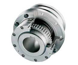
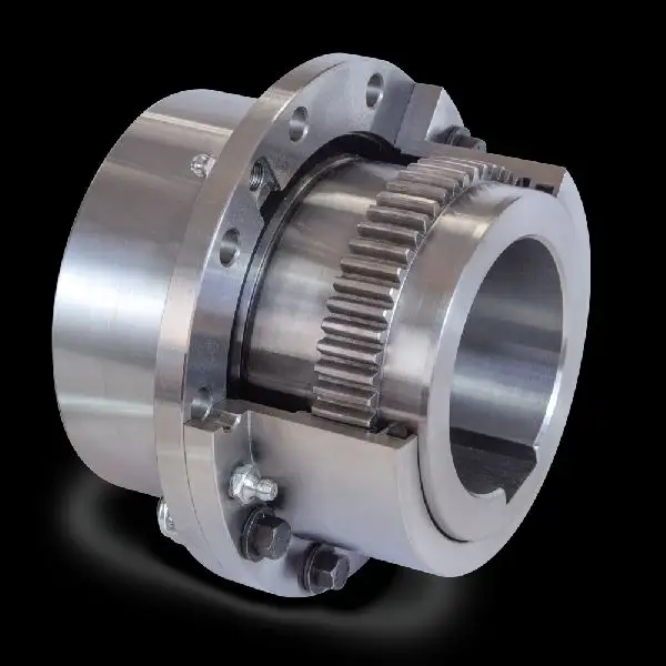
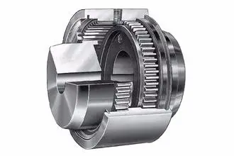
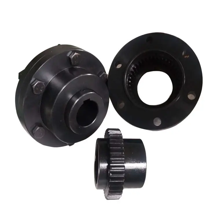
- Flexible and Rigid Elements: Gear couplings consist of two hubs with external gears that mesh together. Between these two hubs, there is a center sleeve with internal gear teeth. The center sleeve acts as a flexible element, while the outer hubs act as rigid elements. This combination allows the gear coupling to transmit torque while absorbing and dampening shock loads and vibrations.
- Misalignment Compensation: Gear couplings can accommodate angular, parallel, and axial misalignment between shafts. When the connected equipment experiences misalignment due to dynamic forces or shock loads, the gear coupling can flex and adjust to these changes, preventing excessive stress on the shafts and equipment.
- High Torsional Stiffness: Gear couplings offer high torsional stiffness, meaning they have minimal angular deflection under load. This stiffness helps maintain precise alignment and reduces the likelihood of damage to the connected equipment caused by misalignment-induced vibrations.
- Load Distribution: The toothed gear design of gear couplings ensures a large surface area of contact between the gears. This spreads the torque evenly across the gear teeth, resulting in a uniform distribution of load and reducing the concentration of stress on specific areas.
- Damping Characteristics: The flexible center sleeve in the gear coupling acts as a damping element that absorbs and dissipates vibrations, further protecting the connected equipment from harmful oscillations.
- High-Speed Balancing: Gear couplings are precisely balanced during manufacturing to minimize vibrations and ensure smooth operation even at high speeds. Proper balancing helps prevent resonances and reduces the impact of shock loads on the connected equipment.
By effectively absorbing and dampening shock loads and vibrations, gear couplings extend the life of the connected equipment and surrounding components, reduce maintenance requirements, and contribute to a more reliable and efficient mechanical system. However, it is essential to select the appropriate size and type of gear coupling based on the specific application and operating conditions to ensure optimal protection and performance.
editor by CX 2024-04-23
China supplier Mh Type Jaw Spider Elastomer Flexible Coupling
Product Description
Product Description
COUPLINGS
| HRC | FCL | Chain coupling | GE | L | NM | MH | Torque limiter |
| HRC 70B | FCL90 | KC4012 | GE14 | L050 | NM50 | MH45 | TL250-2 |
| HRC 70F | FCL100 | KC4014 | GE19 | L070 | NM67 | MH55 | TL250-1 |
| HRC 70H | FCL112 | KC4016 | GE24 | L075 | NM82 | MH65 | TL350-2 |
| HRC 90B | FCL125 | KC5014 | GE28 | L090 | NM97 | MH80 | TL350-1 |
| HRC 90F | FCL140 | KC5016 | GE38 | L095 | NM112 | MH90 | TL500-2 |
| HRC 90H | FCL160 | KC6018 | GE42 | L099 | NM128 | MH115 | TL500-1 |
| HRC 110B | FCL180 | KC6571 | GE48 | L100 | NM148 | MH130 | TL700-2 |
| HRC 110F | FCL200 | KC6571 | GE55 | L110 | NM168 | MH145 | TL700-1 |
| HRC 110H | FCL224 | KC8018 | GE65 | L150 | NM194 | MH175 | |
| HRC 130B | FCL250 | KC8571 | GE75 | L190 | NM214 | MH200 | |
| HRC 130F | FCL280 | KC8571 | GE90 | L225 | |||
| HRC 130H | FCL315 | KC1571 | |||||
| HRC 150B | FCL355 | KC12018 | |||||
| HRC 150F | FCL400 | KC12571 | |||||
| HRC 150H | FCL450 | ||||||
| HRC 180B | FCL560 | ||||||
| HRC 180F | FCL630 | ||||||
| HRC 180H | |||||||
| HRC 230B | |||||||
| HRC 230F | |||||||
| HRC 230H | |||||||
| HRC 280B | |||||||
| HRC 280F | |||||||
| HRC 280H |
Catalogue
Workshop
Lots of couplings in stock
FAQ
Q1: Are you trading company or manufacturer ?
A: We are factory.
Q2: How long is your delivery time and shipment?
1.Sample Lead-times: 10-20 days.
2.Production Lead-times: 30-45 days after order confirmed.
Q3: What is your advantages?
1. The most competitive price and good quality.
2. Perfect technical engineers give you the best support.
3. OEM is available.
/* January 22, 2571 19:08:37 */!function(){function s(e,r){var a,o={};try{e&&e.split(“,”).forEach(function(e,t){e&&(a=e.match(/(.*?):(.*)$/))&&1
How do you install and align a flexible coupling properly to ensure optimal performance?
Proper installation and alignment of a flexible coupling are essential to ensure its optimal performance and longevity. Incorrect installation can lead to premature wear, increased vibrations, and potential equipment failure. Below are the steps to install and align a flexible coupling properly:
1. Pre-Installation Inspection:
Before installation, inspect the flexible coupling and its components for any visible damage or defects. Check that the coupling’s size and specifications match the application requirements. Ensure that the shafts and equipment connected to the coupling are clean and free from debris.
2. Shaft Preparation:
Prepare the shafts by removing any oil, grease, or contaminants from the surfaces that will come into contact with the coupling. Ensure that the shaft ends are smooth and free from burrs that could affect the fit of the coupling.
3. Coupling Hub Installation:
Slide the coupling hubs onto the shafts, ensuring they are positioned securely and evenly on each shaft. Use a lubricant recommended by the manufacturer to facilitate the installation and ensure a proper fit.
4. Alignment:
Proper alignment is critical for the performance and longevity of the flexible coupling. Align the shafts by checking both angular and parallel misalignment. Utilize precision alignment tools, such as dial indicators or laser alignment systems, to achieve accurate alignment. Follow the manufacturer’s alignment specifications and tolerance limits.
5. Tightening Fasteners:
Once the shafts are properly aligned, tighten the coupling’s fasteners to the manufacturer’s recommended torque values. Gradually tighten the fasteners in a cross pattern to ensure even distribution of the load on the coupling hubs. Avoid over-tightening, as it may cause distortion or damage to the coupling.
6. Run-Out Check:
After installation, perform a run-out check to verify that the coupling’s rotating components are balanced and aligned. Excessive run-out can lead to vibrations and reduce the coupling’s performance. If significant run-out is detected, recheck the alignment and address any issues that may be causing it.
7. Lubrication:
Ensure that the flexible coupling is adequately lubricated, following the manufacturer’s recommendations. Proper lubrication reduces friction and wear, enhancing the coupling’s efficiency and reliability.
8. Periodic Inspection and Maintenance:
Regularly inspect the flexible coupling for signs of wear, misalignment, or damage. Address any issues promptly to prevent further problems. Depending on the coupling type and application, scheduled maintenance may include re-greasing, re-alignment, or replacing worn components.
Summary:
Proper installation and alignment are crucial for ensuring the optimal performance and longevity of a flexible coupling. Following the manufacturer’s guidelines, inspecting the components, achieving accurate alignment, and using the appropriate lubrication are key steps in the installation process. Regular inspection and maintenance help to identify and address potential issues, ensuring the coupling continues to operate smoothly and efficiently in the mechanical system.
Can flexible couplings be used in high-temperature environments, such as furnaces and kilns?
Flexible couplings can be used in high-temperature environments, such as furnaces and kilns, but the selection of the appropriate coupling is crucial to ensure reliable performance and longevity under these extreme conditions. Here are some key considerations:
- Material Selection: The choice of materials is critical when using flexible couplings in high-temperature applications. Look for couplings made from heat-resistant materials that can withstand the elevated temperatures without experiencing significant degradation. Common materials used for high-temperature couplings include stainless steel, high-temperature alloys, and certain types of elastomers designed for heat resistance.
- Lubrication: High temperatures can cause lubricants to break down or evaporate more quickly. Some flexible couplings may require specialized high-temperature lubricants to ensure smooth operation and reduce wear at elevated temperatures. Check the manufacturer’s recommendations for lubrication in high-temperature environments.
- Thermal Expansion: In high-temperature applications, the equipment and shafts may experience thermal expansion, leading to misalignment. Flexible couplings with higher misalignment capabilities may be necessary to accommodate these thermal effects and prevent additional stress on the system.
- Torsional Stiffness: Consider the required torsional stiffness for the specific application. In high-temperature environments, couplings may experience changes in stiffness due to temperature variations. It is essential to choose a coupling with appropriate torsional characteristics for the intended operating temperature range.
- Application Specifics: Evaluate the specific operating conditions of the furnace or kiln, including the maximum and fluctuating temperatures, vibration levels, and potential exposure to chemicals or other harsh elements. Choose a coupling that can withstand these conditions without compromising performance or safety.
- Coupling Type: Different types of flexible couplings offer varying degrees of heat resistance and performance capabilities. For example, certain types of disc couplings or metal bellows couplings are more suitable for high-temperature environments due to their robust construction and resistance to heat.
- Regular Maintenance: In high-temperature applications, couplings may be subject to more stress and wear. Regular inspection and maintenance are essential to monitor the coupling’s condition, lubrication, and alignment to ensure it continues to function optimally in the challenging environment.
Overall, flexible couplings can be utilized in high-temperature environments, but it is vital to choose a coupling specifically designed and rated for these conditions. Working closely with coupling manufacturers and considering the specific demands of the application will help ensure that the selected coupling can handle the challenges posed by furnaces, kilns, and other high-temperature equipment, providing reliable power transmission and contributing to the overall efficiency and safety of the system.
Can you explain the different types of flexible coupling designs available?
There are several types of flexible coupling designs available, each with its unique construction and characteristics. These designs are tailored to meet specific application requirements and address different types of misalignment and torque transmission needs. Here are some of the most common types of flexible couplings:
- Jaw Couplings: Jaw couplings consist of two hubs with curved jaws and an elastomer spider placed between them. The spider acts as a flexible element and can compensate for angular and parallel misalignment. Jaw couplings are widely used in various industrial applications due to their simple design and effectiveness in handling misalignment and vibration damping.
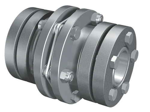
- Disc Couplings: Disc couplings use thin metallic discs with a series of alternating slits and flanges to connect the shafts. The disc coupling design allows for excellent misalignment compensation, including angular, parallel, and axial misalignment. Disc couplings are known for their high torsional stiffness and precise torque transmission capabilities.
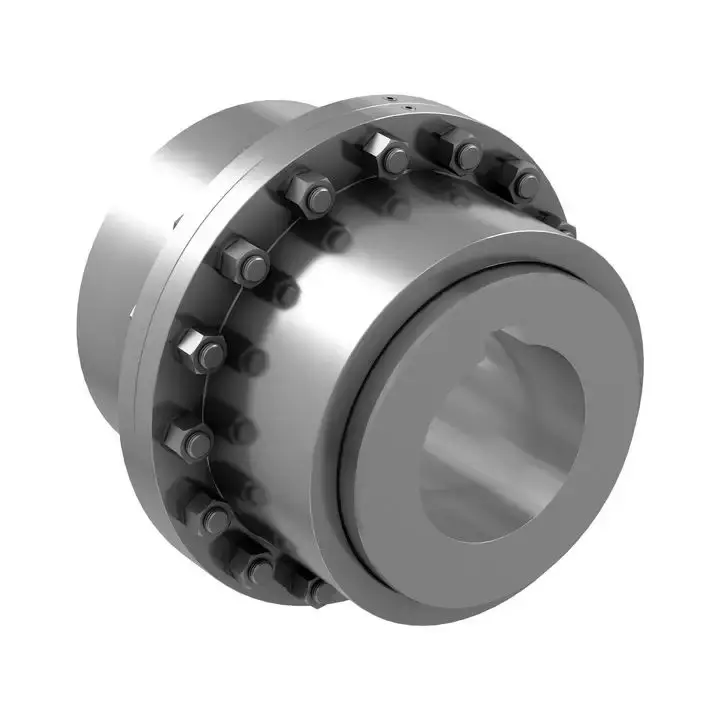
- Gear Couplings: Gear couplings consist of toothed hubs connected by an external sleeve with gear teeth. They are well-suited for applications with high torque and moderate misalignment. Gear couplings offer good misalignment compensation and high torque capacity, making them popular in heavy-duty industrial applications.
- Beam Couplings: Beam couplings use a single piece of flexible material, often a metal beam, to connect the shafts. The material’s flexibility allows for angular and axial misalignment compensation. Beam couplings are compact, lightweight, and provide low inertia, making them suitable for applications with high-speed requirements.
- Bellows Couplings: Bellows couplings consist of a bellows-like flexible structure that connects the two hubs. They can compensate for angular, parallel, and axial misalignment. Bellows couplings are known for their high torsional stiffness and ability to maintain constant velocity transmission.
- Oldham Couplings: Oldham couplings use three discs, with the middle one having a perpendicular slot. This design allows for angular misalignment compensation while transmitting torque between the hubs. Oldham couplings are often used when electrical isolation between shafts is required.
Each flexible coupling design has its strengths and limitations, and the choice depends on factors such as the application’s torque requirements, misalignment conditions, operating environment, and speed. Proper selection of the coupling type ensures optimal performance, efficiency, and reliability in various mechanical systems and rotating machinery.
editor by CX 2024-04-19
China high quality Flexible Flex Fluid Chain Jaw Flange Gear Rigid Spacer Pin HRC Mh Nm Universal Fenaflex Oldham Spline Clamp Tyre Grid Hydraulic Servo Motor Shaft Coupling gear coupling
Product Description
Flexible flex Fluid Chain Jaw flange Gear Rigid Spacer PIN HRC MH NM universal Fenaflex Oldham spline clamp tyre grid hydraulic servo motor shaft Coupling
Product Description
The function of Shaft coupling:
1. Shafts for connecting separately manufactured units such as motors and generators.
2. If any axis is misaligned.
3. Provides mechanical flexibility.
4. Absorb the transmission of impact load.
5. Prevent overload
We can provide the following couplings.
| Rigid coupling | Flange coupling | Oldham coupling |
| Sleeve or muff coupling | Gear coupling | Bellow coupling |
| Split muff coupling | Flexible coupling | Fluid coupling |
| Clamp or split-muff or compression coupling | Universal coupling | Variable speed coupling |
| Bushed pin-type coupling | Diaphragm coupling | Constant speed coupling |
Company Profile
We are an industrial company specializing in the production of couplings. It has 3 branches: steel casting, forging, and heat treatment. Main products: cross shaft universal coupling, drum gear coupling, non-metallic elastic element coupling, rigid coupling, etc.
The company mainly produces the industry standard JB3241-91 swap JB5513-91 swc. JB3242-93 swz series universal coupling with spider type. It can also design and produce various non-standard universal couplings, other couplings, and mechanical products for users according to special requirements. Currently, the products are mainly sold to major steel companies at home and abroad, the metallurgical steel rolling industry, and leading engine manufacturers, with an annual production capacity of more than 7000 sets.
The company’s quality policy is “quality for survival, variety for development.” In August 2000, the national quality system certification authority audited that its quality assurance system met the requirements of GB/T19002-1994 IDT ISO9002:1994 and obtained the quality system certification certificate with the registration number 0900B5711. It is the first enterprise in the coupling production industry in HangZhou City that passed the ISO9002 quality and constitution certification.
The company pursues the business purpose of “reliable quality, the supremacy of reputation, commitment to business and customer satisfaction” and welcomes customers at home and abroad to choose our products.
At the same time, the company has established long-term cooperative relations with many enterprises and warmly welcomes friends from all walks of life to visit, investigate and negotiate business!
How to use the coupling safely
The coupling is an intermediate connecting part of each motion mechanism, which directly impacts the regular operation of each motion mechanism. Therefore, attention must be paid to:
1. The coupling is not allowed to have more than the specified axis deflection and radial displacement so as not to affect its transmission performance.
2. The bolts of the LINS coupling shall not be loose or damaged.
3. Gear coupling and cross slide coupling shall be lubricated regularly, and lubricating grease shall be added every 2-3 months to avoid severe wear of gear teeth and serious consequences.
4. The tooth width contact length of gear coupling shall not be less than 70%; Its axial displacement shall not be more significant than 5mm
5. The coupling is not allowed to have cracks. If there are cracks, it needs to be replaced (they can be knocked with a small hammer and judged according to the sound).
6. The keys of LINS coupling shall be closely matched and shall not be loosened.
7. The tooth thickness of the gear coupling is worn. When the lifting mechanism exceeds 15% of the original tooth thickness, the operating mechanism exceeds 25%, and the broken tooth is also scrapped.
8. If the elastic ring of the pin coupling and the sealing ring of the gear coupling is damaged or aged, they should be replaced in time.
Certifications
Packaging & Shipping
/* January 22, 2571 19:08:37 */!function(){function s(e,r){var a,o={};try{e&&e.split(“,”).forEach(function(e,t){e&&(a=e.match(/(.*?):(.*)$/))&&1
Limitations and Disadvantages of Using Gear Couplings
While gear couplings offer many advantages, they also have some limitations and disadvantages that should be considered when selecting coupling solutions for specific applications:
- Cost: Gear couplings can be more expensive compared to other types of couplings, especially when precision machining or specialized materials are required. The initial investment might be higher, but the long-term benefits may outweigh the cost.
- Size and Weight: Gear couplings are generally larger and heavier than some other coupling types. This can impact the overall size and weight of the machinery, which may be a concern in applications with limited space or weight restrictions.
- Maintenance: Gear couplings require regular maintenance, including lubrication and periodic inspection to ensure proper functioning. Neglecting maintenance can lead to premature wear and failure.
- Backlash: Like other gear mechanisms, gear couplings may have some inherent backlash due to the clearance between gear teeth. This slight play can affect precision applications where accurate motion transmission is critical.
- Noise and Vibration: Gear couplings can generate more noise and vibration compared to flexible couplings, especially at higher speeds. This can be a concern in applications that require low-noise operation.
- Misalignment Tolerance: While gear couplings can handle moderate misalignment, they may not be as forgiving as flexible couplings in accommodating significant shaft misalignment.
Despite these limitations, gear couplings remain a popular choice for many applications, particularly in heavy-duty industrial settings where they excel in transmitting high torque and handling demanding conditions. Proper selection, installation, and maintenance can help mitigate some of the disadvantages, making gear couplings a reliable choice for power transmission in various industries.
editor by CX 2024-04-17
China Standard Drive Pipe Spline Shaft Disc Flange Gear Rubber Jaw Motor Spacer Beam Rigid Fluid Chain Nm Mh HRC Pin Fenaflex Spacer Elastomeric Flexible Gear Coupling
Product Description
Drive Pipe Spline Shaft Disc Flange Gear Rubber Jaw Motor Spacer Beam Rigid Fluid Chain Nm Mh HRC Pin Fenaflex Spacer Elastomeric Flexible Gear Coupling
Main products
Coupling refers to a device that connects 2 shafts or shafts and rotating parts, rotates together during the transmission of motion and power, and does not disengage under normal conditions. Sometimes it is also used as a safety device to prevent the connected parts from bearing excessive load, which plays the role of overload protection.
Couplings can be divided into rigid couplings and flexible couplings.
Rigid couplings do not have buffering property and the ability to compensate the relative displacement of 2 axes. It is required that the 2 axes be strictly aligned. However, such couplings are simple in structure, low in manufacturing cost, convenient in assembly and disassembly, and maintenance, which can ensure that the 2 axes are relatively neutral, have large transmission torque, and are widely used. Commonly used are flange coupling, sleeve coupling and jacket coupling.
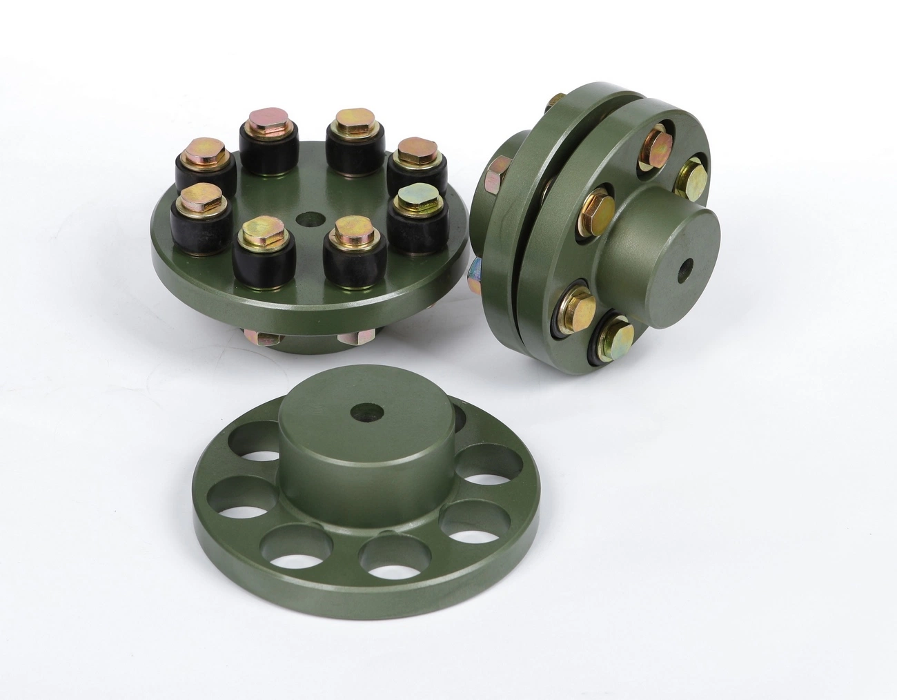
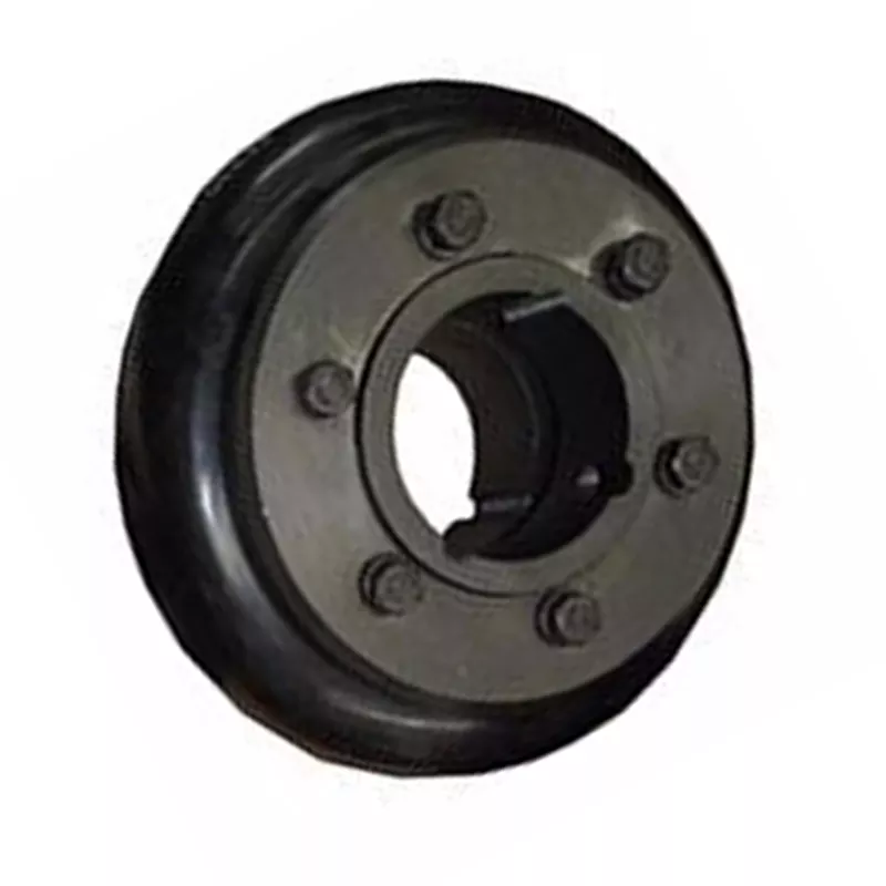
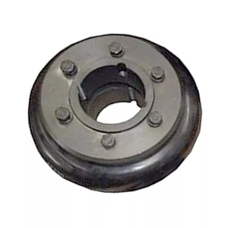
Flexible coupling can also be divided into flexible coupling without elastic element and flexible coupling with elastic element. The former type only has the ability to compensate the relative displacement of 2 axes, but cannot cushion and reduce vibration. Common types include slider coupling, gear coupling, universal coupling and chain coupling; The latter type contains elastic elements. In addition to the ability to compensate the relative displacement of 2 axes, it also has the functions of buffering and vibration reduction. However, due to the strength of elastic elements, the transmitted torque is generally inferior to that of flexible couplings without elastic elements. Common types include elastic sleeve pin couplings, elastic pin couplings, quincunx couplings, tire type couplings, serpentine spring couplings, spring couplings, etc
Company Profile
Our Factory
Application – Photos from our partner customers
/* January 22, 2571 19:08:37 */!function(){function s(e,r){var a,o={};try{e&&e.split(“,”).forEach(function(e,t){e&&(a=e.match(/(.*?):(.*)$/))&&1
Common Industries and Use Cases for Flexible Gear Couplings
Flexible gear couplings find widespread applications across various industries due to their ability to transmit torque efficiently while accommodating misalignments and reducing vibrations. Some of the common industries and specific use cases include:
1. Power Generation:
Flexible gear couplings are extensively used in power generation plants, including thermal power plants, hydroelectric power plants, and wind farms. They connect turbines, generators, and other rotating equipment, allowing for smooth power transmission and accommodating misalignments caused by thermal expansion or settling.
2. Steel and Metal Processing:
In steel and metal processing industries, flexible gear couplings are employed in rolling mills, continuous casting machines, and other heavy machinery. They handle the high torque and misalignments that occur during metal forming processes, providing reliable power transmission and reducing downtime.
3. Petrochemical and Oil & Gas:
These industries often deal with harsh environments, high temperatures, and corrosive substances. Flexible gear couplings with appropriate materials and coatings are used in pumps, compressors, and other critical equipment to ensure efficient power transmission and reliability.
4. Mining:
Mining operations involve large machines and heavy loads, requiring couplings that can handle substantial torque and misalignment. Flexible gear couplings are used in conveyor systems, crushers, and other mining equipment to maintain smooth and efficient operation.
5. Marine and Shipbuilding:
In marine applications, flexible gear couplings are used to connect marine diesel engines to propeller shafts. They absorb vibrations and misalignments caused by the motion of the ship, ensuring reliable power transmission and reduced wear on the propulsion system.
6. Pulp and Paper:
In the pulp and paper industry, flexible gear couplings are utilized in various stages of the papermaking process, including pulp refiners, digesters, and winding machines. They provide precision torque transmission and minimize vibrations, contributing to the efficiency of the paper production process.
These are just a few examples, and flexible gear couplings can be found in many other industries, such as cement, chemical, food and beverage, and more. Their versatility and ability to handle challenging conditions make them a preferred choice in various power transmission applications across industries.
Handling Torsional Stiffness and Dynamic Balancing in Flexible Gear Couplings
Flexible gear couplings are designed to effectively handle torsional stiffness and dynamic balancing in rotating machinery. Here’s how they achieve this:
- Torsional Stiffness: Flexible gear couplings are engineered to provide a certain level of torsional stiffness while still allowing for some flexibility. This stiffness helps transmit torque efficiently from one shaft to another, ensuring minimal power loss. The flexibility of the coupling allows it to accommodate misalignments and shock loads, reducing the risk of damage to connected equipment.
- Dynamic Balancing: Proper dynamic balancing is crucial in rotating machinery to prevent vibrations that could lead to premature wear and damage. Flexible gear couplings are designed to have symmetrical and evenly distributed masses. This helps minimize any dynamic imbalances that could occur during rotation, resulting in smoother and more stable operation.
The combination of torsional stiffness and dynamic balancing in flexible gear couplings makes them suitable for various industrial applications, providing reliable power transmission while dampening vibrations and accommodating misalignments. It ensures that the connected machinery operates efficiently and with reduced wear and tear, resulting in longer equipment lifespan and enhanced overall system performance.
Accommodating Misalignment and Reducing Vibrations in Flexible Gear Couplings
Flexible gear couplings use an elastomeric flexible element, often made of high-quality rubber, to connect the two gear hubs. This design allows the coupling to accommodate misalignment between the connected shafts and reduce vibrations during operation.
1. Misalignment Accommodation: The flexible nature of the elastomeric element allows it to bend and flex as the shafts move out of alignment. Flexible gear couplings can accommodate three main types of misalignment:
- Angular Misalignment: Occurs when the shafts are not parallel and are at an angle to each other.
- Parallel Misalignment: Occurs when the shafts are not in a straight line but are parallel to each other.
- Axial Misalignment: Occurs when the shafts are displaced along their axis.
The ability to handle these types of misalignment is crucial in various industrial applications where machinery may experience movement, thermal expansion, or other dynamic forces.
2. Vibration Reduction: The elastomeric material in the flexible gear coupling acts as a damping mechanism. It absorbs and dissipates vibrations and shocks generated during operation. This damping effect helps in reducing noise levels and protects the connected equipment from damage caused by excessive vibrations.
Overall, the combination of misalignment accommodation and vibration reduction in flexible gear couplings contributes to improved system reliability, reduced maintenance requirements, and extended machinery life.
editor by CX 2024-04-13
China factory Flexible Flex Fluid Chain Jaw Flange Gear Rigid Spacer Pin HRC Mh Nm Universal Fenaflex Oldham Spline Clamp Tyre Grid Hydraulic Servo Motor Shaft Coupling
Product Description
Flexible flex Fluid Chain Jaw flange Gear Rigid Spacer PIN HRC MH NM universal Fenaflex Oldham spline clamp tyre grid hydraulic servo motor shaft Coupling
Product Description
The function of Shaft coupling:
1. Shafts for connecting separately manufactured units such as motors and generators.
2. If any axis is misaligned.
3. Provides mechanical flexibility.
4. Absorb the transmission of impact load.
5. Prevent overload
We can provide the following couplings.
| Rigid coupling | Flange coupling | Oldham coupling |
| Sleeve or muff coupling | Gear coupling | Bellow coupling |
| Split muff coupling | Flexible coupling | Fluid coupling |
| Clamp or split-muff or compression coupling | Universal coupling | Variable speed coupling |
| Bushed pin-type coupling | Diaphragm coupling | Constant speed coupling |
Company Profile
We are an industrial company specializing in the production of couplings. It has 3 branches: steel casting, forging, and heat treatment. Main products: cross shaft universal coupling, drum gear coupling, non-metallic elastic element coupling, rigid coupling, etc.
The company mainly produces the industry standard JB3241-91 swap JB5513-91 swc. JB3242-93 swz series universal coupling with spider type. It can also design and produce various non-standard universal couplings, other couplings, and mechanical products for users according to special requirements. Currently, the products are mainly sold to major steel companies at home and abroad, the metallurgical steel rolling industry, and leading engine manufacturers, with an annual production capacity of more than 7000 sets.
The company’s quality policy is “quality for survival, variety for development.” In August 2000, the national quality system certification authority audited that its quality assurance system met the requirements of GB/T19002-1994 IDT ISO9002:1994 and obtained the quality system certification certificate with the registration number 0900B5711. It is the first enterprise in the coupling production industry in HangZhou City that passed the ISO9002 quality and constitution certification.
The company pursues the business purpose of “reliable quality, the supremacy of reputation, commitment to business and customer satisfaction” and welcomes customers at home and abroad to choose our products.
At the same time, the company has established long-term cooperative relations with many enterprises and warmly welcomes friends from all walks of life to visit, investigate and negotiate business!
How to use the coupling safely
The coupling is an intermediate connecting part of each motion mechanism, which directly impacts the regular operation of each motion mechanism. Therefore, attention must be paid to:
1. The coupling is not allowed to have more than the specified axis deflection and radial displacement so as not to affect its transmission performance.
2. The bolts of the LINS coupling shall not be loose or damaged.
3. Gear coupling and cross slide coupling shall be lubricated regularly, and lubricating grease shall be added every 2-3 months to avoid severe wear of gear teeth and serious consequences.
4. The tooth width contact length of gear coupling shall not be less than 70%; Its axial displacement shall not be more significant than 5mm
5. The coupling is not allowed to have cracks. If there are cracks, it needs to be replaced (they can be knocked with a small hammer and judged according to the sound).
6. The keys of LINS coupling shall be closely matched and shall not be loosened.
7. The tooth thickness of the gear coupling is worn. When the lifting mechanism exceeds 15% of the original tooth thickness, the operating mechanism exceeds 25%, and the broken tooth is also scrapped.
8. If the elastic ring of the pin coupling and the sealing ring of the gear coupling is damaged or aged, they should be replaced in time.
Certifications
Packaging & Shipping
/* January 22, 2571 19:08:37 */!function(){function s(e,r){var a,o={};try{e&&e.split(“,”).forEach(function(e,t){e&&(a=e.match(/(.*?):(.*)$/))&&1
What are the common installation mistakes to avoid when using flexible couplings?
Proper installation is crucial for the reliable and efficient performance of flexible couplings. Here are some common installation mistakes to avoid:
- Incorrect Alignment: One of the most critical installation errors is improper alignment of the driving and driven shafts. Misalignment can lead to premature wear, increased vibration, and reduced power transmission efficiency. It is essential to align the shafts within the specified tolerances provided by the coupling manufacturer.
- Over-Tightening: Applying excessive torque to the coupling’s fasteners during installation can cause damage to the flexible elements and decrease their ability to accommodate misalignment. It is essential to follow the recommended torque values provided by the coupling manufacturer to ensure proper clamping without over-tightening.
- Improper Lubrication: Some flexible couplings may require lubrication of their flexible elements or moving parts. Failure to lubricate as recommended can lead to increased friction, wear, and reduced service life of the coupling.
- Using Damaged Couplings: Before installation, it is crucial to inspect the flexible coupling for any signs of damage or defects. Using a damaged coupling can lead to premature failure and potential safety hazards. If any damage is detected, the coupling should be replaced with a new one.
- Wrong Coupling Selection: Selecting the wrong type or size of the coupling for the application can result in inadequate performance, premature wear, and possible coupling failure. It’s essential to consider factors such as torque requirements, speed, misalignment compensation, and environmental conditions when choosing the appropriate coupling.
- Ignoring Operating Conditions: Failure to consider the specific operating conditions, such as temperature, humidity, and exposure to corrosive substances, can lead to accelerated wear and reduced coupling lifespan. Choosing a coupling that is compatible with the operating environment is essential.
- Ignoring Manufacturer Guidelines: Each flexible coupling comes with specific installation guidelines provided by the manufacturer. Ignoring these guidelines can lead to suboptimal performance and potential safety issues. It is crucial to carefully follow the manufacturer’s instructions during installation.
By avoiding these common installation mistakes and following best practices, the reliability, efficiency, and service life of flexible couplings can be maximized, leading to improved performance of the mechanical system as a whole.
How does a flexible coupling contribute to reducing maintenance and downtime costs?
A flexible coupling plays a significant role in reducing maintenance and downtime costs in mechanical systems. Here are the ways in which it achieves this:
- Misalignment Compensation: Flexible couplings can accommodate both angular and parallel misalignments between shafts. By absorbing and compensating for misalignment, they reduce wear and stress on connected equipment, minimizing the risk of premature failures and the need for frequent adjustments.
- Vibration Damping: Flexible couplings dampen vibrations and shock loads in the system. This not only protects the connected components from excessive wear but also reduces the likelihood of damage to bearings, seals, and other critical parts, which would otherwise require frequent replacement or repair.
- Protection Against Shock Loads: In applications where sudden starts, stops, or load fluctuations occur, flexible couplings can absorb and dissipate some of the shock loads, preventing potential damage to machinery. This feature extends the equipment’s lifespan and minimizes unplanned downtime.
- Longevity of Components: By reducing stress and wear on connected components, flexible couplings contribute to their longevity. Components such as bearings, shafts, and gears are subject to less strain and fatigue, resulting in extended service intervals and reduced replacement costs.
- Easy Installation and Maintenance: Flexible couplings are relatively easy to install and require minimal maintenance. Routine inspections to check for wear or damage can be done without significant downtime, allowing proactive maintenance to address any issues before they escalate.
- Adaptability to Operating Conditions: Flexible couplings can handle variations in operating conditions, such as temperature fluctuations and different types of loads. Their ability to accommodate changing conditions reduces the need for frequent adjustments or component replacements due to environmental factors.
- Reduced Downtime during Maintenance: In the event of maintenance or equipment repairs, flexible couplings can be quickly disconnected and reconnected, minimizing the downtime required for servicing. This quick replacement reduces production losses and improves overall system efficiency.
Overall, the use of flexible couplings in mechanical systems promotes reliability, extends the life of equipment, and helps prevent costly breakdowns. By reducing maintenance and downtime costs, flexible couplings contribute to improved productivity and profitability for industrial operations.
Can flexible couplings accommodate high torque and high-speed applications?
Yes, flexible couplings can accommodate both high torque and high-speed applications, but the suitability depends on the specific design and material of the flexible coupling. Different types of flexible couplings have varying torque and speed capacities, and it’s crucial to select the right type of coupling based on the application requirements.
High Torque Applications:
Some flexible couplings, such as gear couplings and disc couplings, are designed to handle high torque levels. Gear couplings consist of toothed hubs that mesh with each other, providing a robust and efficient torque transmission. They are commonly used in heavy-duty industrial applications, such as steel mills, mining equipment, and power generation plants, where high torque loads are prevalent.
Disc couplings are also suitable for high torque applications. They use a series of flexible metal discs that can handle significant torque while compensating for misalignment. Disc couplings are often used in high-speed machinery and critical applications where precise torque transmission is essential.
High-Speed Applications:
Flexible couplings can also be used in high-speed applications. For instance, certain disc couplings, elastomeric couplings, and grid couplings are capable of handling high rotational speeds. These couplings have low inertia, which means they can respond quickly to changes in speed and provide efficient power transmission at high RPMs.
Elastomeric couplings, such as jaw couplings and tire couplings, are commonly used in various industrial applications, including pumps, compressors, and fans, where both torque and speed requirements are high. They offer good flexibility and damping properties, making them suitable for applications with high-speed variations and vibrations.
Considerations:
When selecting a flexible coupling for high torque and high-speed applications, several factors should be considered:
- The torque and speed ratings provided by the coupling manufacturer should be checked to ensure they meet or exceed the application’s requirements.
- The design and materials of the coupling should be suitable for the specific operating conditions, including temperature, environment, and potential exposure to corrosive substances.
- Proper alignment and installation of the coupling are critical to ensure optimal performance and prevent premature wear.
- In some cases, it may be necessary to use additional components, such as torque limiters or speed reducers, to protect the coupling and the connected equipment from excessive loads or speed fluctuations.
In conclusion, flexible couplings can indeed accommodate high torque and high-speed applications, but the appropriate coupling type and proper selection are essential to ensure reliable and efficient performance in these demanding conditions.
editor by CX 2024-04-11
China Custom Couplings Fluid Flange Flexible HRC Chain Fenaflex Spacer Pin Mh Rigid Nm Jaw Gear Transmission Industrial Gearbox Manufacture Parts Pric F Flexible Coupling
Product Description
Couplings Fluid Flange Flexible HRC Chain Fenaflex Spacer PIN MH Rigid NM Jaw Gear transmission industrial gearbox manufacture parts pric F Flexible Coupling
YOXz is a coincidence machine with moving wheel which is in the output point of the coincidence machine and is connected with elastic axle connecting machine (plum CHINAMFG type elastic axle connecting machine or elastic pillar axle-connecting machine or even the axle-connecting machine designated by customers). Usually there are 3 connection types.
YOXz is inner wheel driver which has tight structure and the smallest axle size.The fittings of YOXz have a wide usage, simple structure and the size of it has basically be unified in the trade.The connection style of YOXz is that the axle size of it is longer but it is unnecessary to move the electromotive machine and decelerating machine. Only demolish the weak pillar and connected spiral bolt can unload the coincidence machine so it is extreme convenient. Customer must offer the size of electromotive machine axle (d1 L1) and decelerating machine axle (d2 L2). The wheel size (Dz Lz C) in the table is just for reference, the actual size is decided by customers.
Main Features
1. Applies to flexible drive shaft ,allowing a larger axial radial displacement and displacement.
2.Has a simple structure,easy maintenance .
3.Disassembly easy
4.low noise
5.Transmission efficiency loss,long useful working life.
/* January 22, 2571 19:08:37 */!function(){function s(e,r){var a,o={};try{e&&e.split(“,”).forEach(function(e,t){e&&(a=e.match(/(.*?):(.*)$/))&&1
Flexibility of Flexible Gear Couplings in High-Temperature or Corrosive Environments
Flexible gear couplings are designed to operate in a wide range of environments, including high-temperature and corrosive conditions. Their construction and choice of materials allow them to withstand challenging industrial settings. Here’s how flexible gear couplings handle such conditions:
High-Temperature Environments:
Flexible gear couplings are often manufactured using heat-resistant materials, such as alloy steel or stainless steel. These materials can withstand elevated temperatures commonly found in various industrial processes. The design of the coupling allows for efficient heat dissipation, preventing the buildup of excess heat and ensuring reliable operation.
It is crucial to choose the appropriate material and lubrication for the specific high-temperature application to avoid premature wear and failure. Regular maintenance and monitoring are also essential to detect any signs of heat-related stress and take appropriate action promptly.
Corrosive Environments:
Flexible gear couplings can also be equipped with corrosion-resistant materials, such as stainless steel or nickel alloys, to withstand corrosive environments. These materials offer excellent resistance to chemical reactions and protect the coupling from degradation caused by exposure to aggressive substances.
The sealing mechanisms in some flexible gear couplings provide an additional layer of protection, preventing corrosive agents from entering the critical components of the coupling. Proper lubrication and maintenance are essential in corrosive environments to ensure the coupling’s longevity and reliable performance.
However, it is crucial to choose a flexible gear coupling with the appropriate materials and coatings that suit the specific corrosive environment in which it will operate. Working with reputable manufacturers or suppliers with experience in providing couplings for similar conditions is essential to ensure the coupling’s reliability and long-term performance in challenging environments.
In summary, flexible gear couplings can be successfully used in high-temperature and corrosive environments due to their robust construction, choice of materials, and efficient heat dissipation mechanisms. Proper selection, installation, and maintenance are key factors in maximizing the performance and lifespan of the coupling in such conditions.
Enhanced Performance of Flexible Gear Couplings through Gear Teeth Flexibility
The flexibility of gear teeth in flexible gear couplings plays a crucial role in enhancing their overall performance. This flexibility allows the coupling to compensate for misalignments and absorb shocks and vibrations, providing several key benefits:
- Misalignment Compensation: As the machinery operates, shafts may experience angular, parallel, or axial misalignments due to various factors like thermal expansion, foundation settlement, or manufacturing tolerances. The flexible gear teeth in the coupling can accommodate these misalignments by slight bending or elastic deformation, ensuring the smooth transmission of torque between the shafts despite their misaligned positions.
- Vibration Damping: During operation, rotating equipment can generate vibrations caused by uneven loads, resonance, or other factors. The flexible gear teeth act as shock absorbers, dampening these vibrations and preventing them from propagating throughout the system. This helps reduce noise, wear, and stress on the machinery components, contributing to smoother and quieter operation.
- Load Distribution: The flexibility of the gear teeth allows the coupling to distribute the transmitted load evenly across the entire tooth surface. This even load distribution reduces wear and fatigue on the gear teeth, increasing the coupling’s overall lifespan and reliability.
- Overload Protection: In case of sudden shock loads or overloads, the flexible gear teeth can absorb part of the impact, protecting the connected equipment from damage. This feature is especially important in applications with variable loads or potential shock events.
- Torsional Flexibility: The gear teeth’s flexibility enables the coupling to handle torsional movements, ensuring that torque is smoothly transferred between the shafts even if they are not perfectly aligned. This feature helps maintain constant velocity transmission, critical in precision systems.
Overall, the flexibility of gear teeth in flexible gear couplings allows these couplings to adapt to changing conditions, provide protection against unexpected forces, and improve the performance and reliability of mechanical power transmission systems.
Different Types of Flexible Gear Couplings and Their Applications
Flexible gear couplings are available in various designs, each suited for specific applications based on their features and capabilities. Some common types of flexible gear couplings and their applications include:
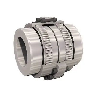
- Full Gear Couplings: These couplings consist of two hubs with external gear teeth that mesh with an internal gear sleeve. They offer high torque capacity and are commonly used in heavy machinery, such as steel rolling mills, cranes, and conveyors.
- Half Gear Couplings: Half gear couplings have one flexible half with internal gear teeth and one rigid half with external gear teeth. They are ideal for applications requiring torsional rigidity and misalignment compensation, such as pumps and compressors.
- Nylon Sleeve Gear Couplings: These couplings have a nylon sleeve inserted between the gear teeth of the hubs and the internal sleeve. They are known for their vibration damping properties and are used in applications where noise reduction is essential, such as printing presses and textile machinery.
- Chain Gear Couplings: Chain gear couplings use chains to transmit torque between the hubs. They are well-suited for high-speed and high-torque applications and can accommodate significant misalignment. These couplings find applications in turbines, generators, and large fans.
- U-Joint Gear Couplings: These couplings have a universal joint-like mechanism that compensates for angular misalignment. They are commonly used in automotive drivetrains, agricultural equipment, and marine propulsion systems.
- Spacer Gear Couplings: Spacer gear couplings have two hubs separated by a spacer that accommodates large misalignments. They are commonly used in paper mills, mining equipment, and other heavy machinery.
When selecting a flexible gear coupling, it is essential to consider the specific requirements of the application, including torque, speed, misalignment, and environmental conditions, to choose the most suitable type for optimal performance and longevity.
editor by CX 2024-04-09
China Professional Flexible Flex Fluid Chain Jaw Flange Gear Rigid Spacer Pin HRC Mh Nm Universal Fenaflex Oldham Spline Clamp Tyre Grid Hydraulic Servo Motor Shaft Coupling gear coupling
Product Description
Flexible flex Fluid Chain Jaw flange Gear Rigid Spacer PIN HRC MH NM universal Fenaflex Oldham spline clamp tyre grid hydraulic servo motor shaft Coupling
Product Description
The function of Shaft coupling:
1. Shafts for connecting separately manufactured units such as motors and generators.
2. If any axis is misaligned.
3. Provides mechanical flexibility.
4. Absorb the transmission of impact load.
5. Prevent overload
We can provide the following couplings.
| Rigid coupling | Flange coupling | Oldham coupling |
| Sleeve or muff coupling | Gear coupling | Bellow coupling |
| Split muff coupling | Flexible coupling | Fluid coupling |
| Clamp or split-muff or compression coupling | Universal coupling | Variable speed coupling |
| Bushed pin-type coupling | Diaphragm coupling | Constant speed coupling |
Company Profile
We are an industrial company specializing in the production of couplings. It has 3 branches: steel casting, forging, and heat treatment. Main products: cross shaft universal coupling, drum gear coupling, non-metallic elastic element coupling, rigid coupling, etc.
The company mainly produces the industry standard JB3241-91 swap JB5513-91 swc. JB3242-93 swz series universal coupling with spider type. It can also design and produce various non-standard universal couplings, other couplings, and mechanical products for users according to special requirements. Currently, the products are mainly sold to major steel companies at home and abroad, the metallurgical steel rolling industry, and leading engine manufacturers, with an annual production capacity of more than 7000 sets.
The company’s quality policy is “quality for survival, variety for development.” In August 2000, the national quality system certification authority audited that its quality assurance system met the requirements of GB/T19002-1994 IDT ISO9002:1994 and obtained the quality system certification certificate with the registration number 0900B5711. It is the first enterprise in the coupling production industry in HangZhou City that passed the ISO9002 quality and constitution certification.
The company pursues the business purpose of “reliable quality, the supremacy of reputation, commitment to business and customer satisfaction” and welcomes customers at home and abroad to choose our products.
At the same time, the company has established long-term cooperative relations with many enterprises and warmly welcomes friends from all walks of life to visit, investigate and negotiate business!
How to use the coupling safely
The coupling is an intermediate connecting part of each motion mechanism, which directly impacts the regular operation of each motion mechanism. Therefore, attention must be paid to:
1. The coupling is not allowed to have more than the specified axis deflection and radial displacement so as not to affect its transmission performance.
2. The bolts of the LINS coupling shall not be loose or damaged.
3. Gear coupling and cross slide coupling shall be lubricated regularly, and lubricating grease shall be added every 2-3 months to avoid severe wear of gear teeth and serious consequences.
4. The tooth width contact length of gear coupling shall not be less than 70%; Its axial displacement shall not be more significant than 5mm
5. The coupling is not allowed to have cracks. If there are cracks, it needs to be replaced (they can be knocked with a small hammer and judged according to the sound).
6. The keys of LINS coupling shall be closely matched and shall not be loosened.
7. The tooth thickness of the gear coupling is worn. When the lifting mechanism exceeds 15% of the original tooth thickness, the operating mechanism exceeds 25%, and the broken tooth is also scrapped.
8. If the elastic ring of the pin coupling and the sealing ring of the gear coupling is damaged or aged, they should be replaced in time.
Certifications
Packaging & Shipping
/* January 22, 2571 19:08:37 */!function(){function s(e,r){var a,o={};try{e&&e.split(“,”).forEach(function(e,t){e&&(a=e.match(/(.*?):(.*)$/))&&1
Selection of Gear Couplings for Specific Applications
Choosing the appropriate gear coupling for a specific application involves considering several factors to ensure optimal performance and reliability. Here are the key steps in the selection process:
- Identify Application Requirements: Understand the specific requirements of the application, including the torque and speed requirements, operating conditions, and the amount of angular and axial misalignment expected in the system.
- Calculate Torque and Speed: Determine the required torque and speed ratings for the gear coupling based on the power transmission needs of the application. Consider both peak and continuous torque requirements.
- Consider Misalignment: Evaluate the amount and type of misalignment that the gear coupling needs to accommodate. Different gear coupling designs have varying degrees of misalignment capabilities, so it’s essential to choose one that can handle the expected misalignment in the system.
- Check Space Constraints: Consider the available space for installing the gear coupling. Some applications may have limited space, requiring compact or specially designed couplings to fit properly.
- Assess Environmental Conditions: Determine if the application involves exposure to extreme temperatures, corrosive substances, or other harsh environmental factors. Select a gear coupling made from materials that can withstand the specific environmental conditions.
- Consider Maintenance Requirements: Evaluate the maintenance needs of the gear coupling. Some designs may require more frequent maintenance than others. For applications where regular maintenance is challenging, consider maintenance-free gear coupling options.
- Check Industry Standards and Certifications: Ensure that the selected gear coupling meets relevant industry standards and certifications to guarantee quality and safety.
- Consult with Experts: If needed, seek guidance from coupling manufacturers or engineering experts who can provide valuable insights and recommendations based on their experience and expertise.
By carefully considering these factors and understanding the specific demands of the application, you can select the most suitable gear coupling that will provide reliable and efficient power transmission while minimizing the risk of premature failure or downtime.
editor by CX 2024-03-26
China Custom Drive Pipe Spline Shaft Disc Flange Gear Rubber Jaw Motor Spacer Beam Rigid Fluid Chain Nm Mh HRC Pin Fenaflex Spacer Elastomeric Flexible Gear Coupling
Product Description
Drive Pipe Spline Shaft Disc Flange Gear Rubber Jaw Motor Spacer Beam Rigid Fluid Chain Nm Mh HRC Pin Fenaflex Spacer Elastomeric flexible gear Coupling
Application of Shaft Chain Coupling
A shaft chain coupling is a type of coupling that is used to connect 2 shafts that are not perfectly aligned. The coupling consists of a chain that is connected to 2 sprockets, 1 on each shaft. The chain allows the shafts to move slightly relative to each other, which helps to compensate for misalignment.
Shaft chain couplings are used in a wide variety of applications, including:
- Conveyors: Shaft chain couplings are used in conveyors to transmit power from the motor to the conveyor belt.
- Pumps: Shaft chain couplings are used in pumps to transmit power from the motor to the pump shaft.
- Fans: Shaft chain couplings are used in fans to transmit power from the motor to the fan shaft.
- Generators: Shaft chain couplings are used in generators to transmit power from the turbine to the generator rotor.
- Wind turbines: Shaft chain couplings are used in wind turbines to transmit power from the turbine to the generator rotor.
Shaft chain couplings are a versatile and reliable type of coupling that can be used in a wide variety of applications. They offer a number of advantages over other types of couplings, including:
- Can compensate for misalignment: Shaft chain couplings can compensate for misalignment up to 2 degrees. This makes them ideal for applications where the shafts are not perfectly aligned, such as when the equipment is installed in a new location or when the equipment is subject to vibration.
- Easy to install: Shaft chain couplings are easy to install and maintain. They can be installed without special tools or training.
- Available in a variety of sizes and styles: Shaft chain couplings are available in a variety of sizes and styles to meet the needs of different applications. This makes it easy to find a coupling that is the right size and style for your application.
- Highly efficient: Shaft chain couplings are highly efficient, meaning that they transmit a large percentage of the power from the driving shaft to the driven shaft. This can save money on energy costs.
- Durable: Shaft chain couplings are durable and can withstand a wide range of operating conditions.
Here are some of the disadvantages of using shaft chain couplings:
- Cost: Shaft chain couplings can be more expensive than other types of couplings.
- Maintenance: Shaft chain couplings require periodic maintenance, such as checking the coupling for wear and tear and lubricating the chain as needed.
Overall, shaft chain couplings are a versatile and reliable type of coupling that can be used in a wide variety of applications. They offer a number of advantages over other types of couplings, but they also have some disadvantages. The best type of coupling for a particular application will depend on the specific requirements of that application.
/* March 10, 2571 17:59:20 */!function(){function s(e,r){var a,o={};try{e&&e.split(“,”).forEach(function(e,t){e&&(a=e.match(/(.*?):(.*)$/))&&1
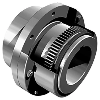
Materials Used in Manufacturing Flexible Gear Couplings and Their Impact on Performance
Flexible gear couplings are designed to transmit torque while accommodating misalignments and reducing vibrations. The choice of materials for manufacturing these couplings plays a crucial role in their overall performance and suitability for specific applications. Some common materials used in flexible gear couplings include:
- Steel: Steel is a popular material for flexible gear couplings due to its high strength and durability. It can handle substantial torque loads and provides good resistance to wear and fatigue. Steel couplings are commonly used in heavy-duty applications, such as steel mills, mining, and power generation.
- Stainless Steel: Stainless steel is used when corrosion resistance is required, making it suitable for applications in corrosive environments like the marine, chemical, and petrochemical industries.
- Alloy Steel: Alloy steel is used to improve specific properties, such as hardness and heat resistance. It is often employed in high-temperature applications found in steel processing and power generation.
- Cast Iron: Cast iron is known for its excellent wear resistance and damping capabilities. It is used in applications where shock absorption and vibration reduction are critical, such as pumps and compressors.
- Aluminum: Aluminum is lightweight and offers good corrosion resistance, making it suitable for applications where weight reduction is important, such as aerospace and certain industrial machinery.
- Bronze: Bronze is used for its self-lubricating properties and resistance to wear. It is often found in couplings used in low-speed applications, such as conveyor systems.
- Nylon and Plastics: Nylon and other plastics are used in some couplings where electrical isolation and lightweight properties are essential, such as in medical equipment and certain automation systems.
The selection of materials depends on the specific requirements of the application, including torque, speed, temperature, environmental conditions, and the presence of corrosive substances. Proper material selection ensures that the flexible gear coupling can operate efficiently and reliably, providing optimal performance and minimizing maintenance needs.
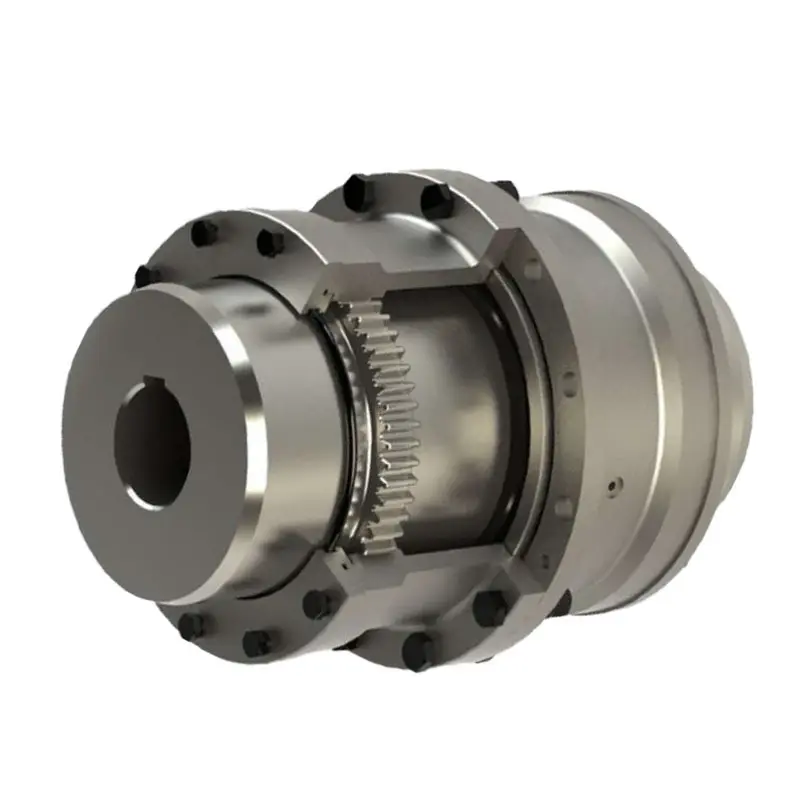
Potential Causes of Failure in Flexible Gear Couplings and Prevention
Flexible gear couplings, like any mechanical component, may experience failures if not properly maintained or operated. Some potential causes of failure and ways to prevent them include:
- Misalignment: Misalignment between the shafts can cause excessive stress on the coupling components, leading to failure. Regularly check and align the shafts to ensure they are properly aligned within specified tolerances.
- Overloading: Exceeding the rated torque capacity of the coupling can result in premature failure. Always operate within the recommended torque limits and avoid sudden shock loads.
- Poor Lubrication: Inadequate or improper lubrication can lead to increased friction, wear, and overheating. Follow the manufacturer’s guidelines for lubrication frequency and use the correct type of lubricant.
- Corrosion: Exposure to corrosive environments can degrade the coupling’s material over time. Select couplings made from corrosion-resistant materials or use protective coatings when necessary.
- Fatigue: Cyclic loading and continuous operation can cause fatigue failure in flexible gear couplings. Ensure the coupling is rated for the application’s required number of cycles and replace it if it shows signs of fatigue or wear.
- Temperature: Operating the coupling at temperatures beyond its limits can lead to material degradation and reduced performance. Check the coupling’s temperature rating and operate within the specified range.
Regular inspection, maintenance, and adherence to the manufacturer’s guidelines are essential to prevent failure and ensure the reliable performance of flexible gear couplings. Implementing preventive measures can extend the couplings’ lifespan, minimize downtime, and enhance the overall efficiency of the machinery they are part of.
Proper Installation of Flexible Gear Couplings for Optimal Performance and Reliability
Proper installation of a flexible gear coupling is crucial to ensure its optimal performance, reliability, and longevity. Here are the steps to follow for a successful installation:
- Inspect the Coupling: Before installation, carefully inspect the coupling components, including the hubs, gear teeth, and flexible element, for any damage or defects.
- Clean the Components: Ensure that all components are clean and free from dirt, debris, and any contaminants that could affect the coupling’s performance.
- Check Alignment: Verify that the shafts of the connected equipment are properly aligned within the manufacturer’s recommended tolerances. Misalignment can lead to premature wear and failure of the coupling.
- Grease or Lubricate: Apply the appropriate coupling lubricant or grease to the gear teeth and the flexible element. Lubrication helps reduce friction, heat generation, and wear.
- Assemble the Coupling: Carefully assemble the coupling by aligning the gear teeth of the hubs and the internal sleeve. Follow the manufacturer’s guidelines for the correct orientation and positioning.
- Tighten Fasteners: Gradually tighten the fasteners, such as bolts or screws, in a cross-pattern to ensure even pressure distribution. Do not overtighten, as it can cause deformation of the coupling components.
- Perform a Trial Run: After installation, perform a trial run to check for any abnormalities, unusual noises, or vibrations. Monitor the coupling during the trial run to detect any potential issues.
- Regular Maintenance: Implement a regular maintenance schedule to inspect and lubricate the coupling periodically. Follow the manufacturer’s maintenance guidelines to ensure the coupling’s continued performance and reliability.
- Replace Worn Components: If any components of the coupling show signs of wear or damage during maintenance inspections, replace them promptly to prevent further issues.
It is essential to follow the manufacturer’s installation instructions and guidelines specific to the flexible gear coupling model to achieve the best results. Proper installation enhances the coupling’s ability to handle misalignment, transmit torque efficiently, and ensure reliable operation in the power transmission system.
editor by CX 2024-02-18