Product Description
Excellent powder metallurgy parts metallic sintered parts
We could offer various powder metallurgy parts including iron based and copper based with top quality and cheapest price, please only send the drawing or sample to us, we will according to customer’s requirement to make it. if you are interested in our product, please do not hesitate to contact us, we would like to offer the top quality and best service for you. thank you!
How do We Work with Our Clients
1. For a design expert or a big company with your own engineering team: we prefer to receive a fully RFQ pack from you including drawing, 3D model, quantity, pictures;
2. For a start-up company owner or green hand for engineering: just send an idea that you want to try, you don’t even need to know what casting is;
3. Our sales will reply you within 24 hours to confirm further details and give the estimated quote time;
4. Our engineering team will evaluate your inquiry and provide our offer within next 1~3 working days.
5. We can arrange a technical communication meeting with you and our engineers together anytime if required.
| Place of origin: | Jangsu,China |
| Type: | Powder metallurgy sintering |
| Spare parts type: | Powder metallurgy parts |
| Machinery Test report: | Provided |
| Material: | Iron,stainless,steel,copper |
| Key selling points: | Quality assurance |
| Mould type: | Tungsten steel |
| Material standard: | MPIF 35,DIN 3571,JIS Z 2550 |
| Application: | Small home appliances,Lockset,Electric tool, automobile, |
| Brand Name: | OEM SERVICE |
| Plating: | Customized |
| After-sales Service: | Online support |
| Processing: | Powder Metallurgr,CNC Machining |
| Powder Metallurgr: | High frequency quenching, oil immersion |
| Quality Control: | 100% inspection |
The Advantage of Powder Metallurgy Process
1. Cost effective
The final products can be compacted with powder metallurgy method ,and no need or can shorten the processing of machine .It can save material greatly and reduce the production cost .
2. Complex shapes
Powder metallurgy allows to obtain complex shapes directly from the compacting tooling ,without any machining operation ,like teeth ,splines ,profiles ,frontal geometries etc.
3. High precision
Achievable tolerances in the perpendicular direction of compacting are typically IT 8-9 as sintered,improvable up to IT 5-7 after sizing .Additional machining operations can improve the precision .
4. Self-lubrication
The interconnected porosity of the material can be filled with oils ,obtaining then a self-lubricating bearing :the oil provides constant lubrication between bearing and shaft ,and the system does not need any additional external lubricant .
5. Green technology
The manufacturing process of sintered components is certified as ecological ,because the material waste is very low ,the product is recyclable ,and the energy efficiency is good because the material is not molten.
FAQ
Q1: What is the type of payment?
A: Usually you should prepay 50% of the total amount. The balance should be pay off before shipment.
Q2: How to guarantee the high quality?
A: 100% inspection. We have Carl Zeiss high-precision testing equipment and testing department to make sure every product of size,appearance and pressure test are good.
Q3: How long will you give me the reply?
A: we will contact you in 12 hours as soon as we can.
Q4. How about your delivery time?
A: Generally, it will take 25 to 35 days after receiving your advance payment. The specific delivery time depends on the items and the quantity of your order. and if the item was non standard, we have to consider extra 10-15days for tooling/mould made.
Q5. Can you produce according to the samples or drawings?
A: Yes, we can produce by your samples or technical drawings. We can build the molds and fixtures.
Q6: How about tooling Charge?
A: Tooling charge only charge once when first order, all future orders would not charge again even tooling repair or under maintance.
Q7: What is your sample policy?
A: We can supply the sample if we have ready parts in stock, but the customers have to pay the sample cost and the courier cost.
Q8: How do you make our business long-term and good relationship?
A: 1. We keep good quality and competitive price to ensure our customers benefit ;
2. We respect every customer as our friend and we sincerely do business and make friends with them, no matter where they come from.
/* January 22, 2571 19:08:37 */!function(){function s(e,r){var a,o={};try{e&&e.split(“,”).forEach(function(e,t){e&&(a=e.match(/(.*?):(.*)$/))&&1
Compensation for Axial, Angular, and Parallel Misalignments with Flexible Gear Couplings
Flexible gear couplings are known for their ability to accommodate various types of misalignments, including axial, angular, and parallel misalignments. Here’s how they compensate for each type:
- Axial Misalignment: Axial misalignment occurs when the two shafts move closer or farther away from each other along the axis of rotation. Flexible gear couplings can absorb this type of misalignment through their flexible design, allowing the gear teeth to articulate and adjust to the axial movement without transmitting harmful forces to the connected equipment.
- Angular Misalignment: Angular misalignment occurs when the two shafts are not collinear and form an angle with each other. Flexible gear couplings can accommodate angular misalignment by allowing the gear teeth to articulate and flex as the shafts are angularly displaced. This flexibility ensures that torque transmission remains smooth and minimizes stress on the coupling and connected equipment.
- Parallel Misalignment: Parallel misalignment happens when the two shafts are offset horizontally while maintaining parallelism. Flexible gear couplings can handle this misalignment by utilizing their flexible elements to adjust to the lateral displacement of the shafts. The ability to compensate for parallel misalignment prevents excessive forces from being transmitted to the machinery, protecting it from damage.
Thanks to their design and material properties, flexible gear couplings provide a reliable solution for compensating for axial, angular, and parallel misalignments, making them suitable for a wide range of applications in various industries.
Comparison of Flexible Gear Couplings with Diaphragm Couplings and Beam Couplings
Flexible gear couplings, diaphragm couplings, and beam couplings are all types of flexible couplings used in mechanical power transmission systems. Each type has its unique characteristics and advantages:
- Flexible Gear Couplings: These couplings consist of gear teeth that mesh together to transmit torque. They are known for their high torque capacity, ability to accommodate misalignment, and torsional stiffness. Flexible gear couplings are commonly used in heavy machinery, such as industrial conveyors and mining equipment, where high torque and misalignment compensation are required.
- Diaphragm Couplings: Diaphragm couplings utilize a thin metal diaphragm to transmit torque between the shafts. They are ideal for applications that demand high precision and no backlash. Diaphragm couplings offer excellent torsional rigidity and can handle axial, angular, and parallel misalignments. They are often used in precision machinery, robotics, and medical equipment.
- Beam Couplings: Beam couplings consist of one or more helical cuts along a cylindrical coupling body. They are known for their flexibility, zero backlash, and compact design. Beam couplings can handle misalignment and are suitable for applications with limited space, such as small motors and positioning systems.
The choice between flexible gear couplings, diaphragm couplings, and beam couplings depends on the specific requirements of the application:
- Flexible gear couplings are preferred for high-torque and heavy-duty applications with substantial misalignments.
- Diaphragm couplings excel in applications where precision and backlash-free operation are critical.
- Beam couplings are suitable for compact systems and applications with limited misalignment.
Each type of coupling has its strengths and limitations, and selecting the most appropriate one depends on factors like torque requirements, misalignment, precision, space constraints, and environmental conditions. Consulting with coupling manufacturers or experts can help in making the right choice for a specific application.
“`
Proper Installation of Flexible Gear Couplings for Optimal Performance and Reliability
Proper installation of a flexible gear coupling is crucial to ensure its optimal performance, reliability, and longevity. Here are the steps to follow for a successful installation:
- Inspect the Coupling: Before installation, carefully inspect the coupling components, including the hubs, gear teeth, and flexible element, for any damage or defects.
- Clean the Components: Ensure that all components are clean and free from dirt, debris, and any contaminants that could affect the coupling’s performance.
- Check Alignment: Verify that the shafts of the connected equipment are properly aligned within the manufacturer’s recommended tolerances. Misalignment can lead to premature wear and failure of the coupling.
- Grease or Lubricate: Apply the appropriate coupling lubricant or grease to the gear teeth and the flexible element. Lubrication helps reduce friction, heat generation, and wear.
- Assemble the Coupling: Carefully assemble the coupling by aligning the gear teeth of the hubs and the internal sleeve. Follow the manufacturer’s guidelines for the correct orientation and positioning.
- Tighten Fasteners: Gradually tighten the fasteners, such as bolts or screws, in a cross-pattern to ensure even pressure distribution. Do not overtighten, as it can cause deformation of the coupling components.
- Perform a Trial Run: After installation, perform a trial run to check for any abnormalities, unusual noises, or vibrations. Monitor the coupling during the trial run to detect any potential issues.
- Regular Maintenance: Implement a regular maintenance schedule to inspect and lubricate the coupling periodically. Follow the manufacturer’s maintenance guidelines to ensure the coupling’s continued performance and reliability.
- Replace Worn Components: If any components of the coupling show signs of wear or damage during maintenance inspections, replace them promptly to prevent further issues.
It is essential to follow the manufacturer’s installation instructions and guidelines specific to the flexible gear coupling model to achieve the best results. Proper installation enhances the coupling’s ability to handle misalignment, transmit torque efficiently, and ensure reliable operation in the power transmission system.


editor by CX 2024-04-30
China Best Sales Transmission Couplings Steel Customized Shaft Hole Motor Spline Gicl Flexible Shaft Drum Gear Coupling
Product Description
Transmission Couplings Steel customized shaft hole Motor Spline GICL Flexible Shaft Drum Gear Coupling
Description:
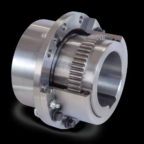
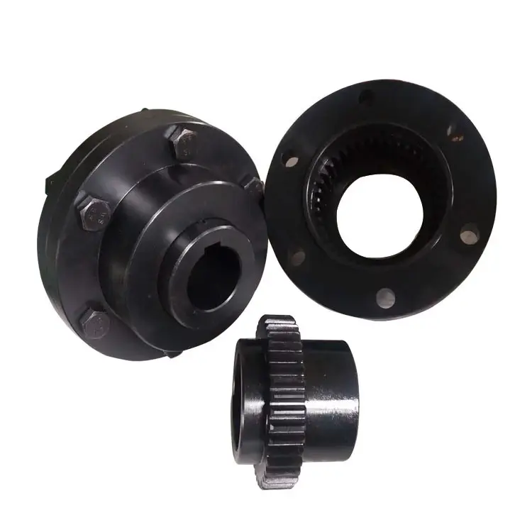
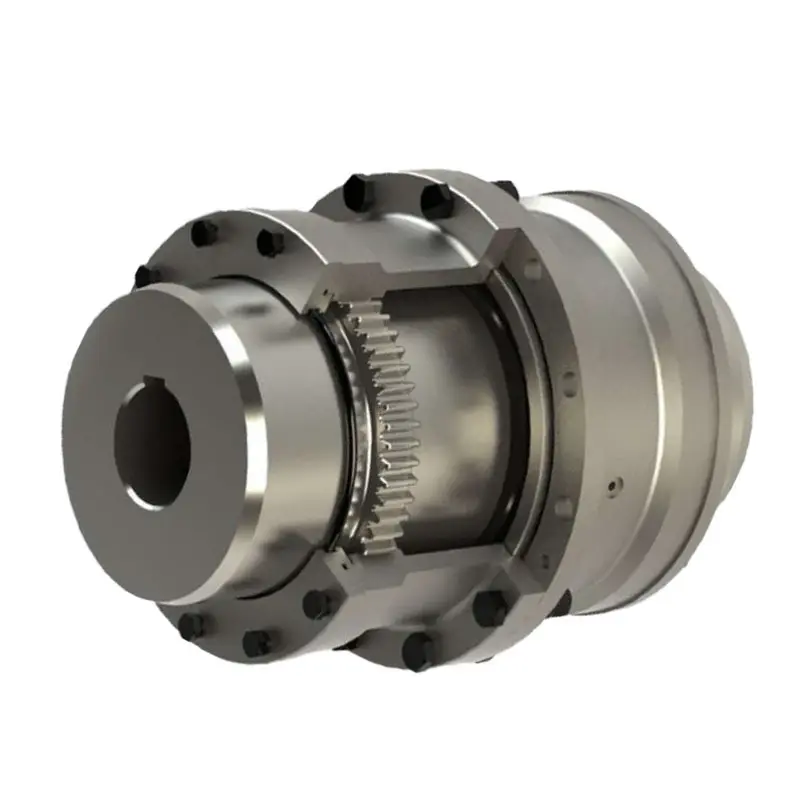
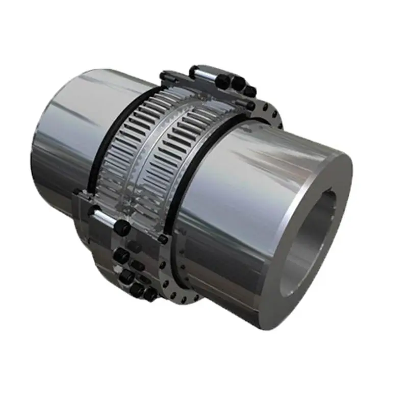
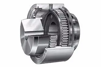
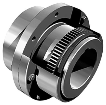
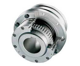
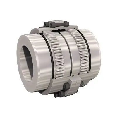
The GICL drum gear coupling consists of a half coupling with the same number of teeth, an inner ring and an outer flange.The outer teeth are straight teeth and 2 kinds of drum teeth. The tooth is the outer sphere of the tooth.
(1)GIICL allows greater angular displacement (relative to straight tooth coupling), which can improve tooth contact conditions, improve transmission torque capacity and extend service life.The contact state of the angular displacement along the tooth width direction.
(2) compensation capability of radial, axial and angular deviation and axial deviation with compact structure, small turning radius, large bearing capacity, high transmission efficiency, low noise and long maintenance cycle;
(3) applicable to low-speed and high-load conditions, such as metallurgy, mining, lifting and transportation industries, as well as the driving shaft, general machinery and other machinery of the petrochemical industry.
Characteristics:
1.Widely used in various mechanical and hydraulic fields
2.Low-cost maintainance
3.Compensation for axial,radial and angular misalignment
4.Convenient axial plugging assembly
5. Installed horizontally and vertically without using any special tools.
6. Excellent mechanical properties
7. No brittlement at low temperature
8. Good sliding and frictional properties
9. Exellent electrical insulation
Parameters:
Packing & shipping:
1 Prevent from damage.
2. As customers’ requirements, in perfect condition.
3. Delivery : As per contract delivery on time
4. Shipping : As per client request. We can accept CIF, Door to Door etc. or client authorized agent we supply all the necessary assistant.
FAQ:
Q 1: Are you a trading company or a manufacturer?
A: We are a professional manufacturer specializing in manufacturing various series of couplings.
Q 2:Can you do OEM?
Yes, we can. We can do OEM & ODM for all the customers with customized artworks in PDF or AI format.
Q 3:How long is your delivery time?
Generally, it is 20-30 days if the goods are not in stock. It is according to quantity.
Q 4: How long is your warranty?
A: Our Warranty is 12 months under normal circumstances.
Q 5: Do you have inspection procedures for coupling?
A:100% self-inspection before packing.
Q 6: Can I have a visit to your factory before the order?
A: Sure, welcome to visit our factory.
/* January 22, 2571 19:08:37 */!function(){function s(e,r){var a,o={};try{e&&e.split(“,”).forEach(function(e,t){e&&(a=e.match(/(.*?):(.*)$/))&&1
Maintenance Requirements for Flexible Gear Couplings
To extend the lifespan and ensure optimal performance of flexible gear couplings, regular maintenance is essential. Here are the key maintenance requirements:
- Lubrication: Proper lubrication is crucial for flexible gear couplings. Regularly inspect the coupling’s lubrication system and ensure it is filled with the recommended lubricant. Adequate lubrication reduces friction, wear, and heat generation, leading to smoother operation and increased lifespan.
- Inspection: Regularly inspect the flexible gear coupling for signs of wear, damage, or misalignment. Look for unusual vibrations, noise, or temperature increases during operation, as these may indicate issues that need attention.
- Torque Monitoring: Periodically check the torque levels to ensure they are within the coupling’s specified limits. Overloading the coupling can lead to premature wear and failure.
- Bolt Tightening: Check and tighten the coupling bolts as needed. Vibrations and continuous operation can cause bolts to loosen over time, affecting the coupling’s performance.
- Alignment: If misalignment is detected during inspection, address it promptly. Proper shaft alignment is crucial for the coupling’s longevity and smooth operation.
- Environmental Considerations: Be mindful of the operating environment. In harsh conditions, such as corrosive or high-temperature environments, additional protective measures may be necessary to safeguard the coupling’s integrity.
Following these maintenance practices will help prevent premature wear, reduce downtime, and extend the lifespan of flexible gear couplings, ensuring reliable and efficient power transmission in the long run.
Handling Torsional Stiffness and Dynamic Balancing in Flexible Gear Couplings
Flexible gear couplings are designed to effectively handle torsional stiffness and dynamic balancing in rotating machinery. Here’s how they achieve this:
- Torsional Stiffness: Flexible gear couplings are engineered to provide a certain level of torsional stiffness while still allowing for some flexibility. This stiffness helps transmit torque efficiently from one shaft to another, ensuring minimal power loss. The flexibility of the coupling allows it to accommodate misalignments and shock loads, reducing the risk of damage to connected equipment.
- Dynamic Balancing: Proper dynamic balancing is crucial in rotating machinery to prevent vibrations that could lead to premature wear and damage. Flexible gear couplings are designed to have symmetrical and evenly distributed masses. This helps minimize any dynamic imbalances that could occur during rotation, resulting in smoother and more stable operation.
The combination of torsional stiffness and dynamic balancing in flexible gear couplings makes them suitable for various industrial applications, providing reliable power transmission while dampening vibrations and accommodating misalignments. It ensures that the connected machinery operates efficiently and with reduced wear and tear, resulting in longer equipment lifespan and enhanced overall system performance.
Advantages of Flexible Gear Couplings
Flexible gear couplings offer several advantages over other types of couplings:
- Misalignment Compensation: Flexible gear couplings can accommodate angular, parallel, and axial misalignments between the connected shafts. This ability to compensate for misalignment reduces stress on the machinery, shafts, and bearings, leading to improved overall system reliability and reduced maintenance requirements.
- Vibration Damping: The elastomeric flexible element in the coupling acts as a damping mechanism, absorbing vibrations and shocks during operation. This feature helps in reducing noise levels and protecting the connected equipment from damage caused by excessive vibrations.
- High Torque Transmission: Flexible gear couplings are designed to handle high torque loads, making them suitable for heavy-duty applications in various industries.
- Compact Design: Compared to some other types of couplings, flexible gear couplings have a relatively compact design, making them suitable for applications with space constraints.
- Easy Installation and Maintenance: The simple design and flexible nature of these couplings make them easy to install and maintain, minimizing downtime and associated costs.
- Reliability: Flexible gear couplings are known for their reliability and long service life, ensuring uninterrupted power transmission in critical industrial processes.
- Torsional Flexibility: The elastomeric material used in the coupling provides high torsional flexibility, enabling smooth torque transmission even in applications with varying loads and speeds.
Overall, the advantages of flexible gear couplings make them a popular choice for power transmission systems in various industries, including mining, steel, paper, and chemical processing, where the demands for performance, reliability, and durability are essential.
editor by CX 2024-04-22
China Standard Transmission Couplings Steel Customized Shaft Hole Motor Spline Gicl Flexible Shaft Drum Gear Coupling
Product Description
Transmission Couplings Steel customized shaft hole Motor Spline GICL Flexible Shaft Drum Gear Coupling
Description:
The GICL drum gear coupling consists of a half coupling with the same number of teeth, an inner ring and an outer flange.The outer teeth are straight teeth and 2 kinds of drum teeth. The tooth is the outer sphere of the tooth.
(1)GIICL allows greater angular displacement (relative to straight tooth coupling), which can improve tooth contact conditions, improve transmission torque capacity and extend service life.The contact state of the angular displacement along the tooth width direction.
(2) compensation capability of radial, axial and angular deviation and axial deviation with compact structure, small turning radius, large bearing capacity, high transmission efficiency, low noise and long maintenance cycle;
(3) applicable to low-speed and high-load conditions, such as metallurgy, mining, lifting and transportation industries, as well as the driving shaft, general machinery and other machinery of the petrochemical industry.
Characteristics:
1.Widely used in various mechanical and hydraulic fields
2.Low-cost maintainance
3.Compensation for axial,radial and angular misalignment
4.Convenient axial plugging assembly
5. Installed horizontally and vertically without using any special tools.
6. Excellent mechanical properties
7. No brittlement at low temperature
8. Good sliding and frictional properties
9. Exellent electrical insulation
Parameters:
Packing & shipping:
1 Prevent from damage.
2. As customers’ requirements, in perfect condition.
3. Delivery : As per contract delivery on time
4. Shipping : As per client request. We can accept CIF, Door to Door etc. or client authorized agent we supply all the necessary assistant.
FAQ:
Q 1: Are you a trading company or a manufacturer?
A: We are a professional manufacturer specializing in manufacturing various series of couplings.
Q 2:Can you do OEM?
Yes, we can. We can do OEM & ODM for all the customers with customized artworks in PDF or AI format.
Q 3:How long is your delivery time?
Generally, it is 20-30 days if the goods are not in stock. It is according to quantity.
Q 4: How long is your warranty?
A: Our Warranty is 12 months under normal circumstances.
Q 5: Do you have inspection procedures for coupling?
A:100% self-inspection before packing.
Q 6: Can I have a visit to your factory before the order?
A: Sure, welcome to visit our factory.
/* January 22, 2571 19:08:37 */!function(){function s(e,r){var a,o={};try{e&&e.split(“,”).forEach(function(e,t){e&&(a=e.match(/(.*?):(.*)$/))&&1
Maintenance Requirements for Flexible Gear Couplings
To extend the lifespan and ensure optimal performance of flexible gear couplings, regular maintenance is essential. Here are the key maintenance requirements:
- Lubrication: Proper lubrication is crucial for flexible gear couplings. Regularly inspect the coupling’s lubrication system and ensure it is filled with the recommended lubricant. Adequate lubrication reduces friction, wear, and heat generation, leading to smoother operation and increased lifespan.
- Inspection: Regularly inspect the flexible gear coupling for signs of wear, damage, or misalignment. Look for unusual vibrations, noise, or temperature increases during operation, as these may indicate issues that need attention.
- Torque Monitoring: Periodically check the torque levels to ensure they are within the coupling’s specified limits. Overloading the coupling can lead to premature wear and failure.
- Bolt Tightening: Check and tighten the coupling bolts as needed. Vibrations and continuous operation can cause bolts to loosen over time, affecting the coupling’s performance.
- Alignment: If misalignment is detected during inspection, address it promptly. Proper shaft alignment is crucial for the coupling’s longevity and smooth operation.
- Environmental Considerations: Be mindful of the operating environment. In harsh conditions, such as corrosive or high-temperature environments, additional protective measures may be necessary to safeguard the coupling’s integrity.
Following these maintenance practices will help prevent premature wear, reduce downtime, and extend the lifespan of flexible gear couplings, ensuring reliable and efficient power transmission in the long run.
Potential Causes of Failure in Flexible Gear Couplings and Prevention
Flexible gear couplings, like any mechanical component, may experience failures if not properly maintained or operated. Some potential causes of failure and ways to prevent them include:
- Misalignment: Misalignment between the shafts can cause excessive stress on the coupling components, leading to failure. Regularly check and align the shafts to ensure they are properly aligned within specified tolerances.
- Overloading: Exceeding the rated torque capacity of the coupling can result in premature failure. Always operate within the recommended torque limits and avoid sudden shock loads.
- Poor Lubrication: Inadequate or improper lubrication can lead to increased friction, wear, and overheating. Follow the manufacturer’s guidelines for lubrication frequency and use the correct type of lubricant.
- Corrosion: Exposure to corrosive environments can degrade the coupling’s material over time. Select couplings made from corrosion-resistant materials or use protective coatings when necessary.
- Fatigue: Cyclic loading and continuous operation can cause fatigue failure in flexible gear couplings. Ensure the coupling is rated for the application’s required number of cycles and replace it if it shows signs of fatigue or wear.
- Temperature: Operating the coupling at temperatures beyond its limits can lead to material degradation and reduced performance. Check the coupling’s temperature rating and operate within the specified range.
Regular inspection, maintenance, and adherence to the manufacturer’s guidelines are essential to prevent failure and ensure the reliable performance of flexible gear couplings. Implementing preventive measures can extend the couplings’ lifespan, minimize downtime, and enhance the overall efficiency of the machinery they are part of.
Industry Standards and Certifications for Flexible Gear Couplings
Flexible gear couplings are essential components in mechanical power transmission systems, and there are industry standards and certifications that govern their design, manufacturing, and performance. Some of the most commonly recognized standards and certifications for flexible gear couplings include:
- ISO 9001: This certification ensures that the manufacturer follows a quality management system that meets international standards, ensuring consistent and reliable production of flexible gear couplings.
- AGMA Standards: The American Gear Manufacturers Association (AGMA) has published various standards related to gear couplings, including AGMA 9002 for flexible couplings, which provides guidelines for design, selection, installation, and lubrication.
- API Standards: The American Petroleum Institute (API) has established standards for couplings used in the oil and gas industry. API 671 specifically covers the requirements for special-purpose couplings, including gear couplings, used in petroleum, chemical, and gas industry services.
- CE Marking: The CE marking indicates that the flexible gear coupling complies with the European Union’s health, safety, and environmental protection standards, making it eligible for sale within the EU market.
- ATEX Certification: If the flexible gear coupling is intended for use in potentially explosive atmospheres, it may require ATEX certification, which ensures compliance with European Union directives for explosive atmosphere protection.
When selecting a flexible gear coupling, it is essential to verify if it conforms to the necessary industry standards and certifications to ensure the coupling’s performance, safety, and reliability in your specific application.
editor by CX 2024-04-11
China Hot selling FCL Flexible Shaft Couplings for Reducer and Motor
Product Description
SC Transmission FCL Flexible Shaft Couplings for Reducer and Motor
Product Description
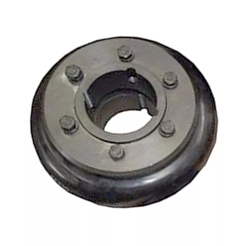
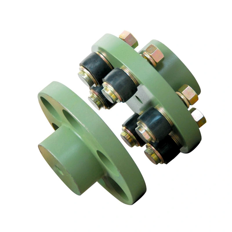
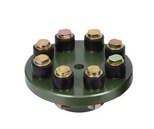
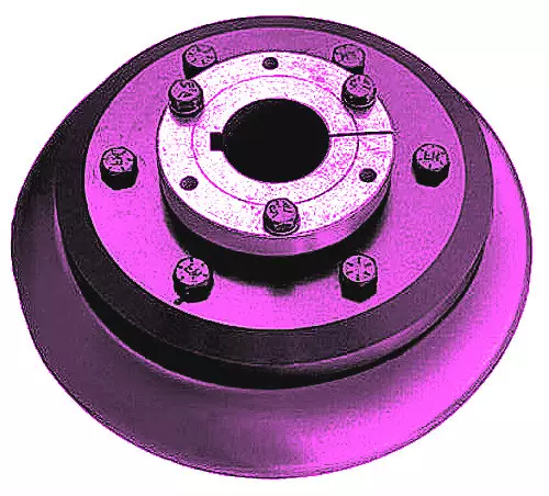
FCL Coupling/Shaft Coupling /Pin & Bush Coupling /FCL Flexible Coupling/NBK FCL Coupling is widely used for its compacts designing, easy installation, convenient maintenance, small and light weight.
As long as the relative displacement between shafts is kept within the specified tolerance, couplings will operate the best function and have a longer working life.
Thus it is greatly demanded in medium and minor power transmission systems driven by motors, such as speed reducers, hoists, compressors, conveyors, spinning and weaving machines and ball mills.
Product Parameters
| SIZE | D | D1 | d1 | L | C | n-M | kg | |||
| r/min | ||||||||||
| N.m | ||||||||||
| FCL90 | 4 | 4000 | 90 | 35.5 | 11 | 28 | 3 | 4-M8 | 1.7 | |
| FCL100 | 10 | 4000 | 100 | 40 | 11 | 35.5 | 3 | 4-M10 | 2.3 | |
| FCL112 | 16 | 4000 | 112 | 45 | 13 | 40 | 3 | 4-M10 | 2.8 | |
| FCL125 | 25 | 4000 | 125 | 65 | 50 | 13 | 45 | 3 | 4-M12 | 4 |
| FCL140 | 50 | 4000 | 140 | 71 | 63 | 13 | 50 | 3 | 6-M12 | 5.4 |
| FCL160 | 110 | 4000 | 160 | 80 | 15 | 56 | 3 | 8-M12 | 8 | |
| FCL180 | 157 | 3500 | 180 | 90 | 15 | 63 | 3 | 8-M12 | 10.5 | |
| FCL200 | 245 | 3200 | 200 | 100 | 21 | 71 | 4 | 8-M20 | 16.2 | |
| FCL224 | 392 | 2850 | 224 | 112 | 21 | 80 | 4 | 8-M20 | 21.3 | |
| FCL250 | 618 | 2550 | 250 | 125 | 25 | 90 | 4 | 8-M24 | 31.6 | |
| FCL280 | 980 | 2300 | 280 | 140 | 34 | 100 | 4 | 8-M24 | 44 | |
| FCL315 | 1568 | 2050 | 315 | 160 | 41 | 112 | 4 | 10-M24 | 57.7 | |
| FCL355 | 2450 | 1800 | 355 | 180 | 60 | 125 | 5 | 8-M30 | 89.5 | |
| FCL400 | 3920 | 1600 | 400 | 200 | 60 | 125 | 5 | 10-M30 | 113 | |
| FCL450 | 6174 | 1400 | 450 | 224 | 65 | 140 | 5 | 12-M30 | 145 | |
| FCL560 | 9800 | 1150 | 560 | 250 | 85 | 160 | 5 | 14-M30 | 229 | |
| FCL630 | 15680 | 1000 | 630 | 280 | 95 | 180 | 5 | 18-M30 | 296 | |
Company Profile
FAQ
Shipping
/* January 22, 2571 19:08:37 */!function(){function s(e,r){var a,o={};try{e&&e.split(“,”).forEach(function(e,t){e&&(a=e.match(/(.*?):(.*)$/))&&1
How do you install and align a flexible coupling properly to ensure optimal performance?
Proper installation and alignment of a flexible coupling are essential to ensure its optimal performance and longevity. Incorrect installation can lead to premature wear, increased vibrations, and potential equipment failure. Below are the steps to install and align a flexible coupling properly:
1. Pre-Installation Inspection:
Before installation, inspect the flexible coupling and its components for any visible damage or defects. Check that the coupling’s size and specifications match the application requirements. Ensure that the shafts and equipment connected to the coupling are clean and free from debris.
2. Shaft Preparation:
Prepare the shafts by removing any oil, grease, or contaminants from the surfaces that will come into contact with the coupling. Ensure that the shaft ends are smooth and free from burrs that could affect the fit of the coupling.
3. Coupling Hub Installation:
Slide the coupling hubs onto the shafts, ensuring they are positioned securely and evenly on each shaft. Use a lubricant recommended by the manufacturer to facilitate the installation and ensure a proper fit.
4. Alignment:
Proper alignment is critical for the performance and longevity of the flexible coupling. Align the shafts by checking both angular and parallel misalignment. Utilize precision alignment tools, such as dial indicators or laser alignment systems, to achieve accurate alignment. Follow the manufacturer’s alignment specifications and tolerance limits.
5. Tightening Fasteners:
Once the shafts are properly aligned, tighten the coupling’s fasteners to the manufacturer’s recommended torque values. Gradually tighten the fasteners in a cross pattern to ensure even distribution of the load on the coupling hubs. Avoid over-tightening, as it may cause distortion or damage to the coupling.
6. Run-Out Check:
After installation, perform a run-out check to verify that the coupling’s rotating components are balanced and aligned. Excessive run-out can lead to vibrations and reduce the coupling’s performance. If significant run-out is detected, recheck the alignment and address any issues that may be causing it.
7. Lubrication:
Ensure that the flexible coupling is adequately lubricated, following the manufacturer’s recommendations. Proper lubrication reduces friction and wear, enhancing the coupling’s efficiency and reliability.
8. Periodic Inspection and Maintenance:
Regularly inspect the flexible coupling for signs of wear, misalignment, or damage. Address any issues promptly to prevent further problems. Depending on the coupling type and application, scheduled maintenance may include re-greasing, re-alignment, or replacing worn components.
Summary:
Proper installation and alignment are crucial for ensuring the optimal performance and longevity of a flexible coupling. Following the manufacturer’s guidelines, inspecting the components, achieving accurate alignment, and using the appropriate lubrication are key steps in the installation process. Regular inspection and maintenance help to identify and address potential issues, ensuring the coupling continues to operate smoothly and efficiently in the mechanical system.
Can flexible couplings be used in the aerospace industry for critical applications?
Flexible couplings can be used in the aerospace industry for certain critical applications, but their usage is limited and carefully considered due to the stringent requirements and safety standards in the aerospace field. Here are some key points to consider:
- Specific Applications: In the aerospace industry, flexible couplings are primarily used in non-flight-critical systems or non-safety-critical applications. They are commonly found in auxiliary equipment, ground support systems, and non-flight propulsion systems.
- Weight and Space Constraints: Weight and space are crucial factors in aerospace applications. Flexible couplings must be lightweight and compact to minimize the impact on the overall weight and size of the aircraft or spacecraft.
- High Reliability Requirements: Aerospace systems demand high reliability and fault tolerance. Flexible couplings used in critical applications must meet stringent reliability standards and undergo rigorous testing and certification to ensure their performance under extreme conditions.
- Material Selection: Aerospace-grade materials are necessary to withstand the demanding environment of aerospace applications. These materials should have high strength-to-weight ratios, corrosion resistance, and excellent mechanical properties to handle the stresses and forces experienced during operation.
- Certifications: Flexible couplings used in the aerospace industry must adhere to specific certifications and standards, such as those set by organizations like the Federal Aviation Administration (FAA) in the United States or the European Union Aviation Safety Agency (EASA) in Europe.
- Redundancy and Safety Measures: In critical systems, redundancy and safety measures are paramount. Flexible couplings used in aerospace applications must be designed with redundancy features to ensure the system’s continued functionality in the event of a failure.
- Temperature and Environmental Considerations: Aerospace systems experience a wide range of temperatures and environmental conditions. Flexible couplings must be able to operate reliably in extreme temperatures, high altitudes, and other challenging environments encountered during flight or space missions.
While flexible couplings have their place in certain aerospace applications, flight-critical and safety-critical systems typically rely on rigid, precision-engineered couplings. These rigid couplings offer higher levels of torque transmission and precision but require careful alignment and installation.
Ultimately, the selection of flexible couplings for aerospace applications must undergo a thorough engineering evaluation and be approved by the relevant regulatory authorities to ensure the highest level of safety and performance in critical aerospace systems.
Can flexible couplings be used for both motor-to-shaft and shaft-to-shaft connections?
Yes, flexible couplings can be used for both motor-to-shaft and shaft-to-shaft connections in various applications. The versatility of flexible couplings allows them to adapt to different types of connections and meet the specific requirements of the system.
Motor-to-Shaft Connections:
When connecting a motor to a shaft, a flexible coupling serves as an intermediary component that joins the motor shaft and the driven shaft. Flexible couplings are commonly used in motor-driven systems to accommodate misalignment between the motor and the driven load. In motor applications, flexible couplings help reduce stress and wear on the motor bearings, thus extending the motor’s life and enhancing overall system reliability. They also act as vibration dampeners, minimizing vibrations transmitted from the motor to the driven shaft, and subsequently to connected equipment, ensuring smoother operation.
Shaft-to-Shaft Connections:
In many mechanical systems, such as those in the manufacturing, automation, and power transmission industries, shaft-to-shaft connections are required. A flexible coupling can bridge the gap between two shafts and transmit torque while accommodating misalignment. This type of coupling is commonly used to connect shafts that are not perfectly aligned due to factors like manufacturing tolerances, thermal expansion, or foundation settling. By allowing for misalignment, the flexible coupling protects the connected components from excessive stresses and ensures efficient power transmission.
Versatility and Advantages:
The ability of flexible couplings to handle both motor-to-shaft and shaft-to-shaft connections makes them versatile solutions for a wide range of industrial applications. Some of the advantages of using flexible couplings in these connections include:
- Minimizing stress and wear on connected components, such as bearings and seals.
- Compensating for misalignment, ensuring smooth power transmission.
- Damping vibrations and shock loads, reducing the risk of mechanical failures.
- Protecting equipment from excessive forces, enhancing system reliability.
- Simplifying installation and alignment procedures, reducing downtime.
- Improving overall system performance and operational efficiency.
Applications:
Flexible couplings find applications in a wide range of industries, including manufacturing, material handling, automotive, aerospace, robotics, and more. Whether connecting a motor to a shaft or joining two shafts directly, flexible couplings play a crucial role in enhancing the reliability and efficiency of rotating machinery and mechanical systems.
In conclusion, flexible couplings can effectively serve as connectors for both motor-to-shaft and shaft-to-shaft connections, providing essential misalignment compensation and protection for connected equipment in various industrial applications.
editor by CX 2024-04-09
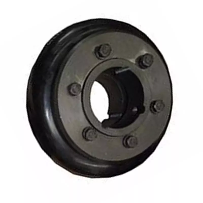
China Best Sales Flange Cast Iron Coupling Steel Universal Joint Cardan Pump Rubber Motor Disc Curved Tooth Flex Rigid Drive Shaft Nm Yox Fluid Jaw Flexible Chain Gear Couplings
Product Description
Flange Cast Iron Coupling Steel Universal Joint Cardan Pump Rubber Motor Disc CHINAMFG Flex Rigid Drive Shaft NM yox Fluid Jaw Flexible Chain Gear Couplings
Manufacturer of Couplings, Fluid Coupling, JAW Coupling, can interchange and replacement of lovejoy coupling and so on.
A coupling can interchange and replacement of lovejoy coupling is a device used to connect 2 shafts together at their ends for the purpose of transmitting power. The primary purpose of couplings is to join 2 pieces of rotating equipment while permitting some degree of misalignment or end movement or both. In a more general context, a coupling can also be a mechanical device that serves to connect the ends of adjacent parts or objects. Couplings do not normally allow disconnection of shafts during operation, however there are torque limiting couplings which can slip or disconnect when some torque limit is exceeded. Selection, installation and maintenance of couplings can lead to reduced maintenance time and maintenance cost.
Coupling is a jaw type coupling that works for a variety of light duty to heavy duty motors used in electric power transmission.
This is 1 of our safest types of products. The reason being that these couplings work even when the elastomer fails and there is no metal to metal contact.
They perform in well-standing oil, grease, moisture, sand, and dirt and nearly 850,000 bore combinations that can be customised as per the customer’s needs.
They are used in light-weight, medium, or heavy electrical motors and devices for power transmission through internal combustion.
Production workshop:
Company information:
/* January 22, 2571 19:08:37 */!function(){function s(e,r){var a,o={};try{e&&e.split(“,”).forEach(function(e,t){e&&(a=e.match(/(.*?):(.*)$/))&&1
Compensation for Axial, Angular, and Parallel Misalignments with Flexible Gear Couplings
Flexible gear couplings are known for their ability to accommodate various types of misalignments, including axial, angular, and parallel misalignments. Here’s how they compensate for each type:
- Axial Misalignment: Axial misalignment occurs when the two shafts move closer or farther away from each other along the axis of rotation. Flexible gear couplings can absorb this type of misalignment through their flexible design, allowing the gear teeth to articulate and adjust to the axial movement without transmitting harmful forces to the connected equipment.
- Angular Misalignment: Angular misalignment occurs when the two shafts are not collinear and form an angle with each other. Flexible gear couplings can accommodate angular misalignment by allowing the gear teeth to articulate and flex as the shafts are angularly displaced. This flexibility ensures that torque transmission remains smooth and minimizes stress on the coupling and connected equipment.
- Parallel Misalignment: Parallel misalignment happens when the two shafts are offset horizontally while maintaining parallelism. Flexible gear couplings can handle this misalignment by utilizing their flexible elements to adjust to the lateral displacement of the shafts. The ability to compensate for parallel misalignment prevents excessive forces from being transmitted to the machinery, protecting it from damage.
Thanks to their design and material properties, flexible gear couplings provide a reliable solution for compensating for axial, angular, and parallel misalignments, making them suitable for a wide range of applications in various industries.
Reduction of Noise and Damping of Vibrations in Mechanical Systems Using Flexible Gear Couplings
Flexible gear couplings can effectively reduce noise and dampen vibrations in mechanical systems due to their unique design and material properties. The key factors contributing to noise reduction and vibration damping are as follows:
- Tooth Profile: Flexible gear couplings use gear teeth with specially designed profiles that help in smoother meshing and engagement. The teeth geometry allows for gradual contact, minimizing impact and noise during torque transmission.
- Metallic Flexibility: The flexibility of the coupling’s metallic components helps in absorbing and dissipating vibrations generated during operation. This flexibility prevents vibrations from propagating throughout the system, reducing overall noise levels.
- Resonance Damping: Flexible gear couplings can dampen resonant vibrations that might occur in the system. Resonance can lead to increased noise and mechanical stress, but the damping effect of the coupling helps to mitigate these issues.
- Torsional Stiffness: While flexible gear couplings offer flexibility, they also provide sufficient torsional stiffness, ensuring smooth and precise torque transmission. This stiffness prevents excessive torsional vibrations from being transmitted to connected components.
- Misalignment Compensation: The ability of flexible gear couplings to accommodate misalignments between shafts further reduces mechanical stress and vibrations, enhancing the overall performance of the system.
Due to these features, flexible gear couplings are commonly used in applications where noise reduction and vibration damping are crucial. They find applications in various industries, including heavy machinery, steel mills, power generation, and pulp and paper manufacturing, where smooth and quiet operation is essential for the efficiency and longevity of the equipment.
Flexible Gear Coupling: Function and Operation
A flexible gear coupling is a type of mechanical coupling used to connect two shafts in a power transmission system. It consists of two hubs with external gear teeth and an elastomeric flexible element between them. The flexible element can be made of materials such as polyurethane, rubber, or synthetic materials with high torsional flexibility and damping properties.
The function of a flexible gear coupling is to transmit torque between the connected shafts while accommodating misalignments and absorbing shocks and vibrations. When the shafts are misaligned due to angular, parallel, or axial displacements, the flexible element allows the hubs to move relative to each other, thus minimizing the transmission of misalignment forces to the connected machinery.
The operation of a flexible gear coupling involves the following steps:
- The torque from the driving shaft is transmitted to the first hub with external gear teeth.
- The external gear teeth on the first hub mesh with the internal gear teeth on the flexible element.
- As the flexible element deforms under torque and misalignment, it allows the second hub to rotate while maintaining contact with the first hub.
- The torque is then transmitted from the flexible element to the second hub, which drives the driven shaft.
The flexibility of the elastomeric element in a flexible gear coupling allows it to dampen vibrations and shocks that may occur during operation, thereby protecting the connected equipment from potential damage. Additionally, its ability to accommodate misalignment reduces stress on the shafts and bearings, extending the life of the power transmission system.
editor by CX 2024-04-08
China high quality Flange Cast Iron Coupling Steel Universal Joint Cardan Pump Rubber Motor Disc Curved Tooth Flex Rigid Drive Shaft Nm Yox Fluid Jaw Flexible Chain Gear Couplings
Product Description
Excellent powder metallurgy parts metallic sintered parts
We could offer various powder metallurgy parts including iron based and copper based with top quality and cheapest price, please only send the drawing or sample to us, we will according to customer’s requirement to make it. if you are interested in our product, please do not hesitate to contact us, we would like to offer the top quality and best service for you. thank you!
How do We Work with Our Clients
1. For a design expert or a big company with your own engineering team: we prefer to receive a fully RFQ pack from you including drawing, 3D model, quantity, pictures;
2. For a start-up company owner or green hand for engineering: just send an idea that you want to try, you don’t even need to know what casting is;
3. Our sales will reply you within 24 hours to confirm further details and give the estimated quote time;
4. Our engineering team will evaluate your inquiry and provide our offer within next 1~3 working days.
5. We can arrange a technical communication meeting with you and our engineers together anytime if required.
| Place of origin: | Jangsu,China |
| Type: | Powder metallurgy sintering |
| Spare parts type: | Powder metallurgy parts |
| Machinery Test report: | Provided |
| Material: | Iron,stainless,steel,copper |
| Key selling points: | Quality assurance |
| Mould type: | Tungsten steel |
| Material standard: | MPIF 35,DIN 3571,JIS Z 2550 |
| Application: | Small home appliances,Lockset,Electric tool, automobile, |
| Brand Name: | OEM SERVICE |
| Plating: | Customized |
| After-sales Service: | Online support |
| Processing: | Powder Metallurgr,CNC Machining |
| Powder Metallurgr: | High frequency quenching, oil immersion |
| Quality Control: | 100% inspection |
The Advantage of Powder Metallurgy Process
1. Cost effective
The final products can be compacted with powder metallurgy method ,and no need or can shorten the processing of machine .It can save material greatly and reduce the production cost .
2. Complex shapes
Powder metallurgy allows to obtain complex shapes directly from the compacting tooling ,without any machining operation ,like teeth ,splines ,profiles ,frontal geometries etc.
3. High precision
Achievable tolerances in the perpendicular direction of compacting are typically IT 8-9 as sintered,improvable up to IT 5-7 after sizing .Additional machining operations can improve the precision .
4. Self-lubrication
The interconnected porosity of the material can be filled with oils ,obtaining then a self-lubricating bearing :the oil provides constant lubrication between bearing and shaft ,and the system does not need any additional external lubricant .
5. Green technology
The manufacturing process of sintered components is certified as ecological ,because the material waste is very low ,the product is recyclable ,and the energy efficiency is good because the material is not molten.
FAQ
Q1: What is the type of payment?
A: Usually you should prepay 50% of the total amount. The balance should be pay off before shipment.
Q2: How to guarantee the high quality?
A: 100% inspection. We have Carl Zeiss high-precision testing equipment and testing department to make sure every product of size,appearance and pressure test are good.
Q3: How long will you give me the reply?
A: we will contact you in 12 hours as soon as we can.
Q4. How about your delivery time?
A: Generally, it will take 25 to 35 days after receiving your advance payment. The specific delivery time depends on the items and the quantity of your order. and if the item was non standard, we have to consider extra 10-15days for tooling/mould made.
Q5. Can you produce according to the samples or drawings?
A: Yes, we can produce by your samples or technical drawings. We can build the molds and fixtures.
Q6: How about tooling Charge?
A: Tooling charge only charge once when first order, all future orders would not charge again even tooling repair or under maintance.
Q7: What is your sample policy?
A: We can supply the sample if we have ready parts in stock, but the customers have to pay the sample cost and the courier cost.
Q8: How do you make our business long-term and good relationship?
A: 1. We keep good quality and competitive price to ensure our customers benefit ;
2. We respect every customer as our friend and we sincerely do business and make friends with them, no matter where they come from.
/* January 22, 2571 19:08:37 */!function(){function s(e,r){var a,o={};try{e&&e.split(“,”).forEach(function(e,t){e&&(a=e.match(/(.*?):(.*)$/))&&1
Common Industries and Use Cases for Flexible Gear Couplings
Flexible gear couplings find widespread applications across various industries due to their ability to transmit torque efficiently while accommodating misalignments and reducing vibrations. Some of the common industries and specific use cases include:
1. Power Generation:
Flexible gear couplings are extensively used in power generation plants, including thermal power plants, hydroelectric power plants, and wind farms. They connect turbines, generators, and other rotating equipment, allowing for smooth power transmission and accommodating misalignments caused by thermal expansion or settling.
2. Steel and Metal Processing:
In steel and metal processing industries, flexible gear couplings are employed in rolling mills, continuous casting machines, and other heavy machinery. They handle the high torque and misalignments that occur during metal forming processes, providing reliable power transmission and reducing downtime.
3. Petrochemical and Oil & Gas:
These industries often deal with harsh environments, high temperatures, and corrosive substances. Flexible gear couplings with appropriate materials and coatings are used in pumps, compressors, and other critical equipment to ensure efficient power transmission and reliability.
4. Mining:
Mining operations involve large machines and heavy loads, requiring couplings that can handle substantial torque and misalignment. Flexible gear couplings are used in conveyor systems, crushers, and other mining equipment to maintain smooth and efficient operation.
5. Marine and Shipbuilding:
In marine applications, flexible gear couplings are used to connect marine diesel engines to propeller shafts. They absorb vibrations and misalignments caused by the motion of the ship, ensuring reliable power transmission and reduced wear on the propulsion system.
6. Pulp and Paper:
In the pulp and paper industry, flexible gear couplings are utilized in various stages of the papermaking process, including pulp refiners, digesters, and winding machines. They provide precision torque transmission and minimize vibrations, contributing to the efficiency of the paper production process.
These are just a few examples, and flexible gear couplings can be found in many other industries, such as cement, chemical, food and beverage, and more. Their versatility and ability to handle challenging conditions make them a preferred choice in various power transmission applications across industries.
Potential Causes of Failure in Flexible Gear Couplings and Prevention
Flexible gear couplings, like any mechanical component, may experience failures if not properly maintained or operated. Some potential causes of failure and ways to prevent them include:
- Misalignment: Misalignment between the shafts can cause excessive stress on the coupling components, leading to failure. Regularly check and align the shafts to ensure they are properly aligned within specified tolerances.
- Overloading: Exceeding the rated torque capacity of the coupling can result in premature failure. Always operate within the recommended torque limits and avoid sudden shock loads.
- Poor Lubrication: Inadequate or improper lubrication can lead to increased friction, wear, and overheating. Follow the manufacturer’s guidelines for lubrication frequency and use the correct type of lubricant.
- Corrosion: Exposure to corrosive environments can degrade the coupling’s material over time. Select couplings made from corrosion-resistant materials or use protective coatings when necessary.
- Fatigue: Cyclic loading and continuous operation can cause fatigue failure in flexible gear couplings. Ensure the coupling is rated for the application’s required number of cycles and replace it if it shows signs of fatigue or wear.
- Temperature: Operating the coupling at temperatures beyond its limits can lead to material degradation and reduced performance. Check the coupling’s temperature rating and operate within the specified range.
Regular inspection, maintenance, and adherence to the manufacturer’s guidelines are essential to prevent failure and ensure the reliable performance of flexible gear couplings. Implementing preventive measures can extend the couplings’ lifespan, minimize downtime, and enhance the overall efficiency of the machinery they are part of.
Accommodating Misalignment and Reducing Vibrations in Flexible Gear Couplings
Flexible gear couplings use an elastomeric flexible element, often made of high-quality rubber, to connect the two gear hubs. This design allows the coupling to accommodate misalignment between the connected shafts and reduce vibrations during operation.
1. Misalignment Accommodation: The flexible nature of the elastomeric element allows it to bend and flex as the shafts move out of alignment. Flexible gear couplings can accommodate three main types of misalignment:
- Angular Misalignment: Occurs when the shafts are not parallel and are at an angle to each other.
- Parallel Misalignment: Occurs when the shafts are not in a straight line but are parallel to each other.
- Axial Misalignment: Occurs when the shafts are displaced along their axis.
The ability to handle these types of misalignment is crucial in various industrial applications where machinery may experience movement, thermal expansion, or other dynamic forces.
2. Vibration Reduction: The elastomeric material in the flexible gear coupling acts as a damping mechanism. It absorbs and dissipates vibrations and shocks generated during operation. This damping effect helps in reducing noise levels and protects the connected equipment from damage caused by excessive vibrations.
Overall, the combination of misalignment accommodation and vibration reduction in flexible gear couplings contributes to improved system reliability, reduced maintenance requirements, and extended machinery life.
editor by CX 2024-03-29
China supplier FCL Flexible Shaft Couplings for Reducer and Motor
Product Description
SC Transmission FCL Flexible Shaft Couplings for Reducer and Motor
Product Description
FCL Coupling/Shaft Coupling /Pin & Bush Coupling /FCL Flexible Coupling/NBK FCL Coupling is widely used for its compacts designing, easy installation, convenient maintenance, small and light weight.
As long as the relative displacement between shafts is kept within the specified tolerance, couplings will operate the best function and have a longer working life.
Thus it is greatly demanded in medium and minor power transmission systems driven by motors, such as speed reducers, hoists, compressors, conveyors, spinning and weaving machines and ball mills.
Product Parameters
| SIZE | D | D1 | d1 | L | C | n-M | kg | |||
| r/min | ||||||||||
| N.m | ||||||||||
| FCL90 | 4 | 4000 | 90 | 35.5 | 11 | 28 | 3 | 4-M8 | 1.7 | |
| FCL100 | 10 | 4000 | 100 | 40 | 11 | 35.5 | 3 | 4-M10 | 2.3 | |
| FCL112 | 16 | 4000 | 112 | 45 | 13 | 40 | 3 | 4-M10 | 2.8 | |
| FCL125 | 25 | 4000 | 125 | 65 | 50 | 13 | 45 | 3 | 4-M12 | 4 |
| FCL140 | 50 | 4000 | 140 | 71 | 63 | 13 | 50 | 3 | 6-M12 | 5.4 |
| FCL160 | 110 | 4000 | 160 | 80 | 15 | 56 | 3 | 8-M12 | 8 | |
| FCL180 | 157 | 3500 | 180 | 90 | 15 | 63 | 3 | 8-M12 | 10.5 | |
| FCL200 | 245 | 3200 | 200 | 100 | 21 | 71 | 4 | 8-M20 | 16.2 | |
| FCL224 | 392 | 2850 | 224 | 112 | 21 | 80 | 4 | 8-M20 | 21.3 | |
| FCL250 | 618 | 2550 | 250 | 125 | 25 | 90 | 4 | 8-M24 | 31.6 | |
| FCL280 | 980 | 2300 | 280 | 140 | 34 | 100 | 4 | 8-M24 | 44 | |
| FCL315 | 1568 | 2050 | 315 | 160 | 41 | 112 | 4 | 10-M24 | 57.7 | |
| FCL355 | 2450 | 1800 | 355 | 180 | 60 | 125 | 5 | 8-M30 | 89.5 | |
| FCL400 | 3920 | 1600 | 400 | 200 | 60 | 125 | 5 | 10-M30 | 113 | |
| FCL450 | 6174 | 1400 | 450 | 224 | 65 | 140 | 5 | 12-M30 | 145 | |
| FCL560 | 9800 | 1150 | 560 | 250 | 85 | 160 | 5 | 14-M30 | 229 | |
| FCL630 | 15680 | 1000 | 630 | 280 | 95 | 180 | 5 | 18-M30 | 296 | |
Company Profile
FAQ
Shipping
/* January 22, 2571 19:08:37 */!function(){function s(e,r){var a,o={};try{e&&e.split(“,”).forEach(function(e,t){e&&(a=e.match(/(.*?):(.*)$/))&&1
How do flexible couplings handle axial movement in rotating machinery?
Flexible couplings are designed to handle different types of misalignments in rotating machinery, including axial movement or axial misalignment. Axial movement occurs when there is displacement along the axis of rotation, causing one shaft to move closer to or away from the other shaft. Here’s how flexible couplings handle axial movement:
- Sliding Capability: Many flexible couplings, especially those with elastomeric elements or certain designs, can slide along the shafts they connect. This sliding capability allows the coupling to accommodate axial movement without introducing additional stress on the connected components. The elastomeric elements can compress or stretch slightly to absorb the axial displacement.
- Multiple-piece Designs: Some flexible couplings consist of multiple pieces, which allow for axial movement. These designs often have a floating member or a spacer that separates the two shaft-connected components. The floating member can move axially as needed, while still transmitting torque and compensating for other misalignments.
- Double-Cardanic Design: Certain high-performance flexible couplings use a double-cardanic design, allowing for misalignment in multiple directions, including axial movement. This design features two sets of flexible elements that work together to accommodate different misalignments and provide a high degree of flexibility.
It’s important to note that while flexible couplings can handle a certain degree of axial movement, excessive axial misalignment might require a different type of coupling or additional measures to be addressed properly.
During the selection and installation process, it’s essential to consider the application’s axial movement requirements and choose a flexible coupling that can accommodate the expected axial displacement while still providing the desired performance, such as vibration damping, shock absorption, or precision motion control.
How does a flexible coupling handle misalignment in large rotating equipment?
Flexible couplings are designed to accommodate various types of misalignment in large rotating equipment, ensuring smooth and efficient power transmission while minimizing stress on connected components. Here’s how flexible couplings handle different types of misalignment:
- Angular Misalignment: Angular misalignment occurs when the axes of the two connected shafts are not collinear and form an angle. Flexible couplings can handle angular misalignment by allowing the coupling elements to flex and move slightly, thus accommodating the angle between the shafts. The flexible elements, often made of elastomeric materials or metallic membranes, can bend and twist to compensate for angular misalignment, ensuring that the coupling remains engaged and transfers torque effectively.
- Parallel Misalignment: Parallel misalignment, also known as offset misalignment, happens when the two shafts are not perfectly aligned along their axes, resulting in a lateral shift. Flexible couplings can handle parallel misalignment through their ability to move radially, allowing the flexible elements to adjust and take up the offset. This capability prevents excessive side loads on the shafts and bearings, reducing wear and increasing the lifespan of the equipment.
- Axial Misalignment: Axial misalignment occurs when there is a linear displacement of one shaft relative to the other, either toward or away from the other shaft. Some flexible couplings, such as certain types of flexible disc couplings, can accommodate a limited amount of axial misalignment. However, for large axial movement, other types of couplings or special designs may be required.
The flexibility of the coupling elements allows them to act as a buffer between the shafts, dampening shocks, vibrations, and torsional forces caused by misalignment or other dynamic loads. This helps protect the connected equipment from damage and enhances the overall performance and reliability of the rotating system.
In large rotating equipment, where misalignment is more common due to thermal expansion, foundation settling, or other factors, flexible couplings play a critical role in maintaining smooth operation and reducing stress on the machinery. However, it is essential to choose the appropriate type of flexible coupling based on the specific requirements of the application and to regularly inspect and maintain the coupling to ensure optimal performance and longevity.
How does a flexible coupling protect connected equipment from shock loads and vibrations?
Flexible couplings play a crucial role in protecting connected equipment from shock loads and vibrations by providing damping and isolation capabilities. When machines or mechanical systems experience sudden shock loads or vibrations, the flexible coupling acts as a buffer, absorbing and dissipating the impact, thereby reducing the transmitted forces and protecting the equipment. Here’s how flexible couplings achieve this:
- Damping of Vibrations: Flexible couplings are often made from materials that exhibit damping properties. When vibrations are transmitted through the shafts, the flexible coupling’s material can absorb a portion of the vibrational energy, converting it into heat. This dissipation of energy helps reduce the amplitude of the vibrations and prevents them from propagating further into the connected equipment.
- Vibration Isolation: In addition to damping vibrations, flexible couplings also offer a degree of vibration isolation. They are designed to decouple the two shafts, which means that vibrations occurring on one shaft are not directly transmitted to the other shaft. This isolation effect prevents vibrations from propagating across the entire system and minimizes the impact on sensitive equipment or nearby components.
- Shock Absorption: When the connected machinery experiences sudden shock loads, such as during a startup or abrupt changes in load, the flexible coupling can act as a shock absorber. The coupling’s design allows it to deform slightly under the impact, absorbing and distributing the shock energy. This prevents the shock from being directly transferred to the connected equipment, reducing the risk of damage or premature wear.
- Misalignment Compensation: Flexible couplings are capable of compensating for misalignment between the shafts. Misalignment can lead to additional stresses and vibrations in the system. By allowing for some degree of angular, parallel, and axial misalignment, the flexible coupling reduces the forces transmitted to the connected equipment and the supporting structures.
- Reduction of Resonance Effects: Resonance is a phenomenon that occurs when the natural frequency of a system matches the frequency of external vibrations, leading to amplified vibrations. Flexible couplings can help avoid resonance effects by altering the system’s natural frequency and providing some level of flexibility that damps the resonance response.
By incorporating a flexible coupling into the drivetrain or power transmission system, equipment manufacturers and operators can significantly improve the reliability and longevity of connected machinery. The coupling’s ability to dampen vibrations, isolate shocks, and compensate for misalignment contributes to a smoother and more stable operation, reducing maintenance requirements and enhancing overall system performance.
In summary, flexible couplings act as protective elements, shielding connected equipment from shock loads and vibrations. Their ability to dampen vibrations, isolate shocks, and compensate for misalignment contributes to a smoother and more reliable operation of various mechanical systems.
editor by CX 2024-03-04
China Hot selling Flange Cast Iron Coupling Steel Universal Joint Cardan Pump Rubber Motor Disc Curved Tooth Flex Rigid Drive Shaft Nm Yox Fluid Jaw Flexible Chain Gear Couplings
Product Description
Excellent powder metallurgy parts metallic sintered parts
We could offer various powder metallurgy parts including iron based and copper based with top quality and cheapest price, please only send the drawing or sample to us, we will according to customer’s requirement to make it. if you are interested in our product, please do not hesitate to contact us, we would like to offer the top quality and best service for you. thank you!
How do We Work with Our Clients
1. For a design expert or a big company with your own engineering team: we prefer to receive a fully RFQ pack from you including drawing, 3D model, quantity, pictures;
2. For a start-up company owner or green hand for engineering: just send an idea that you want to try, you don’t even need to know what casting is;
3. Our sales will reply you within 24 hours to confirm further details and give the estimated quote time;
4. Our engineering team will evaluate your inquiry and provide our offer within next 1~3 working days.
5. We can arrange a technical communication meeting with you and our engineers together anytime if required.
| Place of origin: | Jangsu,China |
| Type: | Powder metallurgy sintering |
| Spare parts type: | Powder metallurgy parts |
| Machinery Test report: | Provided |
| Material: | Iron,stainless,steel,copper |
| Key selling points: | Quality assurance |
| Mould type: | Tungsten steel |
| Material standard: | MPIF 35,DIN 3571,JIS Z 2550 |
| Application: | Small home appliances,Lockset,Electric tool, automobile, |
| Brand Name: | OEM SERVICE |
| Plating: | Customized |
| After-sales Service: | Online support |
| Processing: | Powder Metallurgr,CNC Machining |
| Powder Metallurgr: | High frequency quenching, oil immersion |
| Quality Control: | 100% inspection |
The Advantage of Powder Metallurgy Process
1. Cost effective
The final products can be compacted with powder metallurgy method ,and no need or can shorten the processing of machine .It can save material greatly and reduce the production cost .
2. Complex shapes
Powder metallurgy allows to obtain complex shapes directly from the compacting tooling ,without any machining operation ,like teeth ,splines ,profiles ,frontal geometries etc.
3. High precision
Achievable tolerances in the perpendicular direction of compacting are typically IT 8-9 as sintered,improvable up to IT 5-7 after sizing .Additional machining operations can improve the precision .
4. Self-lubrication
The interconnected porosity of the material can be filled with oils ,obtaining then a self-lubricating bearing :the oil provides constant lubrication between bearing and shaft ,and the system does not need any additional external lubricant .
5. Green technology
The manufacturing process of sintered components is certified as ecological ,because the material waste is very low ,the product is recyclable ,and the energy efficiency is good because the material is not molten.
FAQ
Q1: What is the type of payment?
A: Usually you should prepay 50% of the total amount. The balance should be pay off before shipment.
Q2: How to guarantee the high quality?
A: 100% inspection. We have Carl Zeiss high-precision testing equipment and testing department to make sure every product of size,appearance and pressure test are good.
Q3: How long will you give me the reply?
A: we will contact you in 12 hours as soon as we can.
Q4. How about your delivery time?
A: Generally, it will take 25 to 35 days after receiving your advance payment. The specific delivery time depends on the items and the quantity of your order. and if the item was non standard, we have to consider extra 10-15days for tooling/mould made.
Q5. Can you produce according to the samples or drawings?
A: Yes, we can produce by your samples or technical drawings. We can build the molds and fixtures.
Q6: How about tooling Charge?
A: Tooling charge only charge once when first order, all future orders would not charge again even tooling repair or under maintance.
Q7: What is your sample policy?
A: We can supply the sample if we have ready parts in stock, but the customers have to pay the sample cost and the courier cost.
Q8: How do you make our business long-term and good relationship?
A: 1. We keep good quality and competitive price to ensure our customers benefit ;
2. We respect every customer as our friend and we sincerely do business and make friends with them, no matter where they come from.
/* March 10, 2571 17:59:20 */!function(){function s(e,r){var a,o={};try{e&&e.split(“,”).forEach(function(e,t){e&&(a=e.match(/(.*?):(.*)$/))&&1
Compensation for Axial, Angular, and Parallel Misalignments with Flexible Gear Couplings
Flexible gear couplings are known for their ability to accommodate various types of misalignments, including axial, angular, and parallel misalignments. Here’s how they compensate for each type:
- Axial Misalignment: Axial misalignment occurs when the two shafts move closer or farther away from each other along the axis of rotation. Flexible gear couplings can absorb this type of misalignment through their flexible design, allowing the gear teeth to articulate and adjust to the axial movement without transmitting harmful forces to the connected equipment.
- Angular Misalignment: Angular misalignment occurs when the two shafts are not collinear and form an angle with each other. Flexible gear couplings can accommodate angular misalignment by allowing the gear teeth to articulate and flex as the shafts are angularly displaced. This flexibility ensures that torque transmission remains smooth and minimizes stress on the coupling and connected equipment.
- Parallel Misalignment: Parallel misalignment happens when the two shafts are offset horizontally while maintaining parallelism. Flexible gear couplings can handle this misalignment by utilizing their flexible elements to adjust to the lateral displacement of the shafts. The ability to compensate for parallel misalignment prevents excessive forces from being transmitted to the machinery, protecting it from damage.
Thanks to their design and material properties, flexible gear couplings provide a reliable solution for compensating for axial, angular, and parallel misalignments, making them suitable for a wide range of applications in various industries.
Comparison of Flexible Gear Couplings with Diaphragm Couplings and Beam Couplings
Flexible gear couplings, diaphragm couplings, and beam couplings are all types of flexible couplings used in mechanical power transmission systems. Each type has its unique characteristics and advantages:
- Flexible Gear Couplings: These couplings consist of gear teeth that mesh together to transmit torque. They are known for their high torque capacity, ability to accommodate misalignment, and torsional stiffness. Flexible gear couplings are commonly used in heavy machinery, such as industrial conveyors and mining equipment, where high torque and misalignment compensation are required.
- Diaphragm Couplings: Diaphragm couplings utilize a thin metal diaphragm to transmit torque between the shafts. They are ideal for applications that demand high precision and no backlash. Diaphragm couplings offer excellent torsional rigidity and can handle axial, angular, and parallel misalignments. They are often used in precision machinery, robotics, and medical equipment.
- Beam Couplings: Beam couplings consist of one or more helical cuts along a cylindrical coupling body. They are known for their flexibility, zero backlash, and compact design. Beam couplings can handle misalignment and are suitable for applications with limited space, such as small motors and positioning systems.
The choice between flexible gear couplings, diaphragm couplings, and beam couplings depends on the specific requirements of the application:
- Flexible gear couplings are preferred for high-torque and heavy-duty applications with substantial misalignments.
- Diaphragm couplings excel in applications where precision and backlash-free operation are critical.
- Beam couplings are suitable for compact systems and applications with limited misalignment.
Each type of coupling has its strengths and limitations, and selecting the most appropriate one depends on factors like torque requirements, misalignment, precision, space constraints, and environmental conditions. Consulting with coupling manufacturers or experts can help in making the right choice for a specific application.
“`
Industry Standards and Certifications for Flexible Gear Couplings
Flexible gear couplings are essential components in mechanical power transmission systems, and there are industry standards and certifications that govern their design, manufacturing, and performance. Some of the most commonly recognized standards and certifications for flexible gear couplings include:
- ISO 9001: This certification ensures that the manufacturer follows a quality management system that meets international standards, ensuring consistent and reliable production of flexible gear couplings.
- AGMA Standards: The American Gear Manufacturers Association (AGMA) has published various standards related to gear couplings, including AGMA 9002 for flexible couplings, which provides guidelines for design, selection, installation, and lubrication.
- API Standards: The American Petroleum Institute (API) has established standards for couplings used in the oil and gas industry. API 671 specifically covers the requirements for special-purpose couplings, including gear couplings, used in petroleum, chemical, and gas industry services.
- CE Marking: The CE marking indicates that the flexible gear coupling complies with the European Union’s health, safety, and environmental protection standards, making it eligible for sale within the EU market.
- ATEX Certification: If the flexible gear coupling is intended for use in potentially explosive atmospheres, it may require ATEX certification, which ensures compliance with European Union directives for explosive atmosphere protection.
When selecting a flexible gear coupling, it is essential to verify if it conforms to the necessary industry standards and certifications to ensure the coupling’s performance, safety, and reliability in your specific application.
editor by CX 2024-02-25
China wholesaler FCL Flexible Shaft Couplings for Reducer and Motor
Product Description
SC Transmission FCL Flexible Shaft Couplings for Reducer and Motor
Product Description
FCL Coupling/Shaft Coupling /Pin & Bush Coupling /FCL Flexible Coupling/NBK FCL Coupling is widely used for its compacts designing, easy installation, convenient maintenance, small and light weight.
As long as the relative displacement between shafts is kept within the specified tolerance, couplings will operate the best function and have a longer working life.
Thus it is greatly demanded in medium and minor power transmission systems driven by motors, such as speed reducers, hoists, compressors, conveyors, spinning and weaving machines and ball mills.
Product Parameters
| SIZE | D | D1 | d1 | L | C | n-M | kg | |||
| r/min | ||||||||||
| N.m | ||||||||||
| FCL90 | 4 | 4000 | 90 | 35.5 | 11 | 28 | 3 | 4-M8 | 1.7 | |
| FCL100 | 10 | 4000 | 100 | 40 | 11 | 35.5 | 3 | 4-M10 | 2.3 | |
| FCL112 | 16 | 4000 | 112 | 45 | 13 | 40 | 3 | 4-M10 | 2.8 | |
| FCL125 | 25 | 4000 | 125 | 65 | 50 | 13 | 45 | 3 | 4-M12 | 4 |
| FCL140 | 50 | 4000 | 140 | 71 | 63 | 13 | 50 | 3 | 6-M12 | 5.4 |
| FCL160 | 110 | 4000 | 160 | 80 | 15 | 56 | 3 | 8-M12 | 8 | |
| FCL180 | 157 | 3500 | 180 | 90 | 15 | 63 | 3 | 8-M12 | 10.5 | |
| FCL200 | 245 | 3200 | 200 | 100 | 21 | 71 | 4 | 8-M20 | 16.2 | |
| FCL224 | 392 | 2850 | 224 | 112 | 21 | 80 | 4 | 8-M20 | 21.3 | |
| FCL250 | 618 | 2550 | 250 | 125 | 25 | 90 | 4 | 8-M24 | 31.6 | |
| FCL280 | 980 | 2300 | 280 | 140 | 34 | 100 | 4 | 8-M24 | 44 | |
| FCL315 | 1568 | 2050 | 315 | 160 | 41 | 112 | 4 | 10-M24 | 57.7 | |
| FCL355 | 2450 | 1800 | 355 | 180 | 60 | 125 | 5 | 8-M30 | 89.5 | |
| FCL400 | 3920 | 1600 | 400 | 200 | 60 | 125 | 5 | 10-M30 | 113 | |
| FCL450 | 6174 | 1400 | 450 | 224 | 65 | 140 | 5 | 12-M30 | 145 | |
| FCL560 | 9800 | 1150 | 560 | 250 | 85 | 160 | 5 | 14-M30 | 229 | |
| FCL630 | 15680 | 1000 | 630 | 280 | 95 | 180 | 5 | 18-M30 | 296 | |
Company Profile
FAQ
Shipping
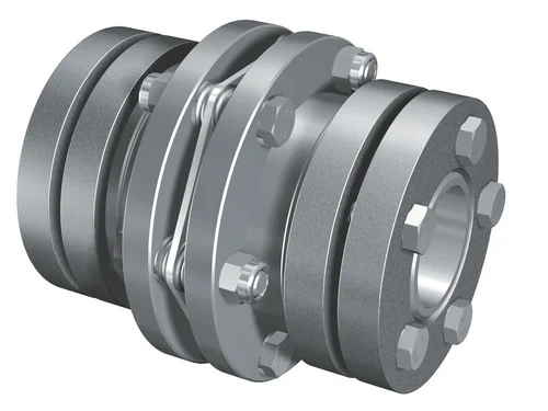
What are the common installation mistakes to avoid when using flexible couplings?
Proper installation is crucial for the reliable and efficient performance of flexible couplings. Here are some common installation mistakes to avoid:
- Incorrect Alignment: One of the most critical installation errors is improper alignment of the driving and driven shafts. Misalignment can lead to premature wear, increased vibration, and reduced power transmission efficiency. It is essential to align the shafts within the specified tolerances provided by the coupling manufacturer.
- Over-Tightening: Applying excessive torque to the coupling’s fasteners during installation can cause damage to the flexible elements and decrease their ability to accommodate misalignment. It is essential to follow the recommended torque values provided by the coupling manufacturer to ensure proper clamping without over-tightening.
- Improper Lubrication: Some flexible couplings may require lubrication of their flexible elements or moving parts. Failure to lubricate as recommended can lead to increased friction, wear, and reduced service life of the coupling.
- Using Damaged Couplings: Before installation, it is crucial to inspect the flexible coupling for any signs of damage or defects. Using a damaged coupling can lead to premature failure and potential safety hazards. If any damage is detected, the coupling should be replaced with a new one.
- Wrong Coupling Selection: Selecting the wrong type or size of the coupling for the application can result in inadequate performance, premature wear, and possible coupling failure. It’s essential to consider factors such as torque requirements, speed, misalignment compensation, and environmental conditions when choosing the appropriate coupling.
- Ignoring Operating Conditions: Failure to consider the specific operating conditions, such as temperature, humidity, and exposure to corrosive substances, can lead to accelerated wear and reduced coupling lifespan. Choosing a coupling that is compatible with the operating environment is essential.
- Ignoring Manufacturer Guidelines: Each flexible coupling comes with specific installation guidelines provided by the manufacturer. Ignoring these guidelines can lead to suboptimal performance and potential safety issues. It is crucial to carefully follow the manufacturer’s instructions during installation.
By avoiding these common installation mistakes and following best practices, the reliability, efficiency, and service life of flexible couplings can be maximized, leading to improved performance of the mechanical system as a whole.
What are the factors influencing the thermal performance of a flexible coupling?
The thermal performance of a flexible coupling can be influenced by several factors, including:
- Material Composition: The material used in the construction of the flexible coupling can impact its thermal performance. Different materials have varying thermal conductivity and heat resistance properties, which can affect how well the coupling dissipates heat generated during operation.
- Operating Speed: The rotational speed of the flexible coupling can influence its thermal behavior. Higher speeds can result in increased friction, leading to more heat generation. Couplings designed for high-speed applications often incorporate features to manage and dissipate heat effectively.
- Power Transmission: The amount of power transmitted through the flexible coupling plays a role in its thermal performance. Higher power levels can lead to increased heat generation, and the coupling must be designed to handle and dissipate this heat without compromising its integrity.
- Environmental Conditions: The ambient temperature and surrounding environment can impact the thermal performance of the flexible coupling. In high-temperature environments, the coupling may need to dissipate heat more efficiently to avoid overheating.
- Lubrication: Proper lubrication is essential for managing friction and heat generation within the coupling. Insufficient or inappropriate lubrication can lead to increased wear and heat buildup.
- Design and Geometry: The design and geometry of the flexible coupling can influence its thermal performance. Some coupling designs incorporate features such as cooling fins, ventilation, or heat sinks to enhance heat dissipation.
- Load Distribution: The distribution of loads across the flexible coupling can affect how heat is generated and dissipated. Proper load distribution helps prevent localized heating and reduces the risk of thermal issues.
Manufacturers consider these factors during the design and selection of flexible couplings to ensure they can handle the thermal demands of specific applications. Proper application and maintenance of the flexible coupling are also essential for optimizing its thermal performance and overall efficiency.
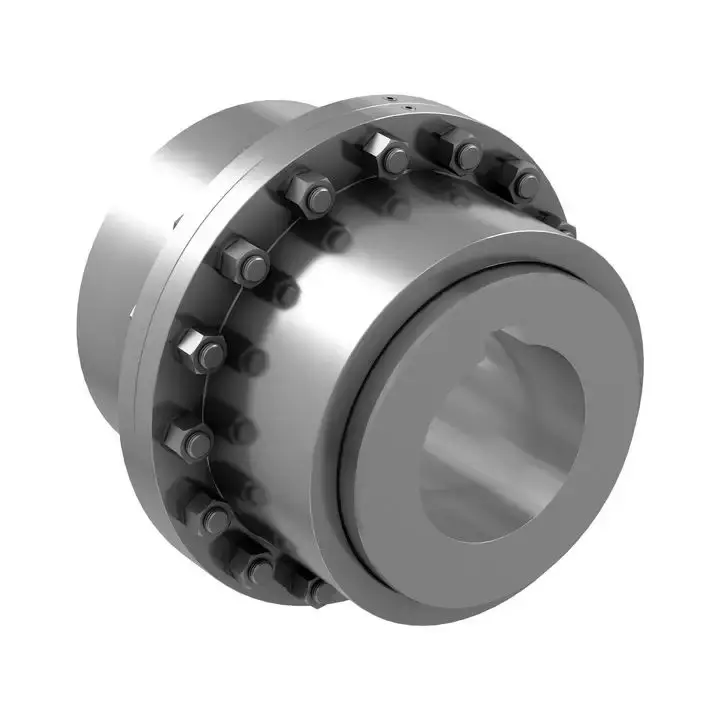
What materials are commonly used in manufacturing flexible couplings?
Flexible couplings are manufactured using a variety of materials, each offering different properties and characteristics suited for specific applications. The choice of material depends on factors such as the application’s requirements, environmental conditions, torque capacity, and desired flexibility. Here are some of the commonly used materials in manufacturing flexible couplings:
- Steel: Steel is a widely used material in flexible couplings due to its strength, durability, and excellent torque transmission capabilities. Steel couplings are suitable for heavy-duty industrial applications with high torque requirements and harsh operating conditions.
- Stainless Steel: Stainless steel is often used to manufacture flexible couplings in environments with high corrosion potential. Stainless steel couplings offer excellent resistance to rust and other corrosive elements, making them ideal for marine, food processing, and chemical industry applications.
- Aluminum: Aluminum couplings are lightweight, have low inertia, and provide excellent balance. They are commonly used in applications where reducing weight is critical, such as aerospace and robotics.
- Brass: Brass couplings are known for their electrical conductivity and are used in applications where electrical grounding or electrical isolation is required, such as in certain industrial machinery or electronics equipment.
- Cast Iron: Cast iron couplings offer good strength and durability and are often used in industrial applications where resistance to shock loads and vibrations is necessary.
- Plastic/Polymer: Some flexible couplings use high-performance polymers or plastics, such as polyurethane or nylon. These materials provide good flexibility, low friction, and resistance to chemicals. Plastic couplings are suitable for applications where corrosion resistance and lightweight are essential.
- Elastomers: Elastomers are used as the flexible elements in many flexible couplings. Materials like natural rubber, neoprene, or urethane are commonly used as elastomer spider elements, providing flexibility and vibration damping properties.
The selection of the coupling material depends on the specific needs of the application. For instance, high-performance and heavy-duty applications may require steel or stainless steel couplings for their robustness, while applications where weight reduction is crucial may benefit from aluminum or polymer couplings. Additionally, the choice of material is influenced by factors such as temperature range, chemical exposure, and electrical requirements in the application’s operating environment.
Manufacturers typically provide material specifications for their couplings, helping users make informed decisions based on the specific demands of their applications.
editor by CX 2023-11-16