Product Description
Product Description
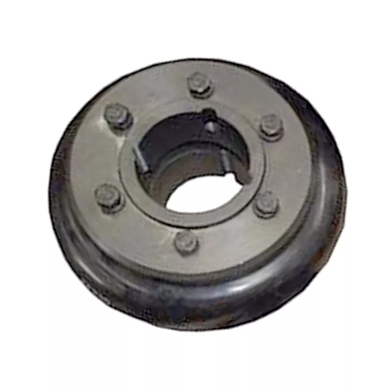
COUPLINGS
| HRC | FCL | Chain coupling | GE | L | NM | MH | Torque limiter |
| HRC 70B | FCL90 | KC4012 | GE14 | L050 | NM50 | MH45 | TL250-2 |
| HRC 70F | FCL100 | KC4014 | GE19 | L070 | NM67 | MH55 | TL250-1 |
| HRC 70H | FCL112 | KC4016 | GE24 | L075 | NM82 | MH65 | TL350-2 |
| HRC 90B | FCL125 | KC5014 | GE28 | L090 | NM97 | MH80 | TL350-1 |
| HRC 90F | FCL140 | KC5016 | GE38 | L095 | NM112 | MH90 | TL500-2 |
| HRC 90H | FCL160 | KC6018 | GE42 | L099 | NM128 | MH115 | TL500-1 |
| HRC 110B | FCL180 | KC6571 | GE48 | L100 | NM148 | MH130 | TL700-2 |
| HRC 110F | FCL200 | KC6571 | GE55 | L110 | NM168 | MH145 | TL700-1 |
| HRC 110H | FCL224 | KC8018 | GE65 | L150 | NM194 | MH175 | |
| HRC 130B | FCL250 | KC8571 | GE75 | L190 | NM214 | MH200 | |
| HRC 130F | FCL280 | KC8571 | GE90 | L225 | |||
| HRC 130H | FCL315 | KC1571 | |||||
| HRC 150B | FCL355 | KC12018 | |||||
| HRC 150F | FCL400 | KC12571 | |||||
| HRC 150H | FCL450 | ||||||
| HRC 180B | FCL560 | ||||||
| HRC 180F | FCL630 | ||||||
| HRC 180H | |||||||
| HRC 230B | |||||||
| HRC 230F | |||||||
| HRC 230H | |||||||
| HRC 280B | |||||||
| HRC 280F | |||||||
| HRC 280H |
Catalogue
Workshop
Lots of couplings in stock
FAQ
Q1: Are you trading company or manufacturer ?
A: We are factory.
Q2: How long is your delivery time and shipment?
1.Sample Lead-times: 10-20 days.
2.Production Lead-times: 30-45 days after order confirmed.
Q3: What is your advantages?
1. The most competitive price and good quality.
2. Perfect technical engineers give you the best support.
3. OEM is available.
/* January 22, 2571 19:08:37 */!function(){function s(e,r){var a,o={};try{e&&e.split(“,”).forEach(function(e,t){e&&(a=e.match(/(.*?):(.*)$/))&&1
How do you install and align a flexible coupling properly to ensure optimal performance?
Proper installation and alignment of a flexible coupling are essential to ensure its optimal performance and longevity. Incorrect installation can lead to premature wear, increased vibrations, and potential equipment failure. Below are the steps to install and align a flexible coupling properly:
1. Pre-Installation Inspection:
Before installation, inspect the flexible coupling and its components for any visible damage or defects. Check that the coupling’s size and specifications match the application requirements. Ensure that the shafts and equipment connected to the coupling are clean and free from debris.
2. Shaft Preparation:
Prepare the shafts by removing any oil, grease, or contaminants from the surfaces that will come into contact with the coupling. Ensure that the shaft ends are smooth and free from burrs that could affect the fit of the coupling.
3. Coupling Hub Installation:
Slide the coupling hubs onto the shafts, ensuring they are positioned securely and evenly on each shaft. Use a lubricant recommended by the manufacturer to facilitate the installation and ensure a proper fit.
4. Alignment:
Proper alignment is critical for the performance and longevity of the flexible coupling. Align the shafts by checking both angular and parallel misalignment. Utilize precision alignment tools, such as dial indicators or laser alignment systems, to achieve accurate alignment. Follow the manufacturer’s alignment specifications and tolerance limits.
5. Tightening Fasteners:
Once the shafts are properly aligned, tighten the coupling’s fasteners to the manufacturer’s recommended torque values. Gradually tighten the fasteners in a cross pattern to ensure even distribution of the load on the coupling hubs. Avoid over-tightening, as it may cause distortion or damage to the coupling.
6. Run-Out Check:
After installation, perform a run-out check to verify that the coupling’s rotating components are balanced and aligned. Excessive run-out can lead to vibrations and reduce the coupling’s performance. If significant run-out is detected, recheck the alignment and address any issues that may be causing it.
7. Lubrication:
Ensure that the flexible coupling is adequately lubricated, following the manufacturer’s recommendations. Proper lubrication reduces friction and wear, enhancing the coupling’s efficiency and reliability.
8. Periodic Inspection and Maintenance:
Regularly inspect the flexible coupling for signs of wear, misalignment, or damage. Address any issues promptly to prevent further problems. Depending on the coupling type and application, scheduled maintenance may include re-greasing, re-alignment, or replacing worn components.
Summary:
Proper installation and alignment are crucial for ensuring the optimal performance and longevity of a flexible coupling. Following the manufacturer’s guidelines, inspecting the components, achieving accurate alignment, and using the appropriate lubrication are key steps in the installation process. Regular inspection and maintenance help to identify and address potential issues, ensuring the coupling continues to operate smoothly and efficiently in the mechanical system.
Can flexible couplings be used in high-temperature environments, such as furnaces and kilns?
Flexible couplings can be used in high-temperature environments, such as furnaces and kilns, but the selection of the appropriate coupling is crucial to ensure reliable performance and longevity under these extreme conditions. Here are some key considerations:
- Material Selection: The choice of materials is critical when using flexible couplings in high-temperature applications. Look for couplings made from heat-resistant materials that can withstand the elevated temperatures without experiencing significant degradation. Common materials used for high-temperature couplings include stainless steel, high-temperature alloys, and certain types of elastomers designed for heat resistance.
- Lubrication: High temperatures can cause lubricants to break down or evaporate more quickly. Some flexible couplings may require specialized high-temperature lubricants to ensure smooth operation and reduce wear at elevated temperatures. Check the manufacturer’s recommendations for lubrication in high-temperature environments.
- Thermal Expansion: In high-temperature applications, the equipment and shafts may experience thermal expansion, leading to misalignment. Flexible couplings with higher misalignment capabilities may be necessary to accommodate these thermal effects and prevent additional stress on the system.
- Torsional Stiffness: Consider the required torsional stiffness for the specific application. In high-temperature environments, couplings may experience changes in stiffness due to temperature variations. It is essential to choose a coupling with appropriate torsional characteristics for the intended operating temperature range.
- Application Specifics: Evaluate the specific operating conditions of the furnace or kiln, including the maximum and fluctuating temperatures, vibration levels, and potential exposure to chemicals or other harsh elements. Choose a coupling that can withstand these conditions without compromising performance or safety.
- Coupling Type: Different types of flexible couplings offer varying degrees of heat resistance and performance capabilities. For example, certain types of disc couplings or metal bellows couplings are more suitable for high-temperature environments due to their robust construction and resistance to heat.
- Regular Maintenance: In high-temperature applications, couplings may be subject to more stress and wear. Regular inspection and maintenance are essential to monitor the coupling’s condition, lubrication, and alignment to ensure it continues to function optimally in the challenging environment.
Overall, flexible couplings can be utilized in high-temperature environments, but it is vital to choose a coupling specifically designed and rated for these conditions. Working closely with coupling manufacturers and considering the specific demands of the application will help ensure that the selected coupling can handle the challenges posed by furnaces, kilns, and other high-temperature equipment, providing reliable power transmission and contributing to the overall efficiency and safety of the system.
Can you explain the different types of flexible coupling designs available?
There are several types of flexible coupling designs available, each with its unique construction and characteristics. These designs are tailored to meet specific application requirements and address different types of misalignment and torque transmission needs. Here are some of the most common types of flexible couplings:
- Jaw Couplings: Jaw couplings consist of two hubs with curved jaws and an elastomer spider placed between them. The spider acts as a flexible element and can compensate for angular and parallel misalignment. Jaw couplings are widely used in various industrial applications due to their simple design and effectiveness in handling misalignment and vibration damping.
- Disc Couplings: Disc couplings use thin metallic discs with a series of alternating slits and flanges to connect the shafts. The disc coupling design allows for excellent misalignment compensation, including angular, parallel, and axial misalignment. Disc couplings are known for their high torsional stiffness and precise torque transmission capabilities.
- Gear Couplings: Gear couplings consist of toothed hubs connected by an external sleeve with gear teeth. They are well-suited for applications with high torque and moderate misalignment. Gear couplings offer good misalignment compensation and high torque capacity, making them popular in heavy-duty industrial applications.
- Beam Couplings: Beam couplings use a single piece of flexible material, often a metal beam, to connect the shafts. The material’s flexibility allows for angular and axial misalignment compensation. Beam couplings are compact, lightweight, and provide low inertia, making them suitable for applications with high-speed requirements.
- Bellows Couplings: Bellows couplings consist of a bellows-like flexible structure that connects the two hubs. They can compensate for angular, parallel, and axial misalignment. Bellows couplings are known for their high torsional stiffness and ability to maintain constant velocity transmission.
- Oldham Couplings: Oldham couplings use three discs, with the middle one having a perpendicular slot. This design allows for angular misalignment compensation while transmitting torque between the hubs. Oldham couplings are often used when electrical isolation between shafts is required.
Each flexible coupling design has its strengths and limitations, and the choice depends on factors such as the application’s torque requirements, misalignment conditions, operating environment, and speed. Proper selection of the coupling type ensures optimal performance, efficiency, and reliability in various mechanical systems and rotating machinery.


editor by CX 2024-04-19